To begin with, Full Duplex Audio Line Circuit is like a strong talking line, where two people can talk at a same time on one wire like a phone call.
Not like a walkie talkie where only one person talk and other wait; but with full duplex both people talk anytime like a actual talking.
Circuit Working:
Parts List:
| Components | Values | Quantity |
|---|---|---|
| Resistors (All resistors are 1/4 watt unless specified) | 220k | 1 |
| 2.2k | 1 | |
| 200k | 1 | |
| 47k | 2 | |
| 100k | 6 | |
| Preset 10k | 1 | |
| Capacitors | Ceramic 0.27 µF | 2 |
| 2.2µF | 2 | |
| Trimmer 100pF | 1 | |
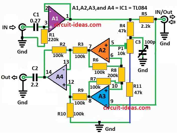
| Semiconductors | IC A1, A2, A3, A4 = IC1 TL084 | 1 |
Circuit working with simple and basic idea:
Two transmitters, one on each side, send signals through the wire and the wire voltage becomes the sum of both signals, like U1 + U2.
But in actual circuit, it is more like half that sum; each side takes out own signal and ignore the other one so both sides need same circuit.
Here, Op amp A1 works like helper and it changes impedance and send signal and Resistor R5 is like guard it protect A1 from other signal coming back from other side.
Signals mix together at output and this mix connects to op-amps A2, A3 and A4 and they work like brain to understand signal.
The right signal comes out through divider R4, R11, and P1 and the OUT pin picks it from the mixed signal; also this method rejects unwanted same-phase signals, but it needs very accurate resistors.
With good resistors noise goes down a lot like 80dB at 1kHz and 60dB at 20kHz and if cable is long and noise is still there, then one can adjust C3 to make it better.
To set it up right first connect signal generator to IN and send 5kHz sine wave with 1V and then connect twisted pair wire to IN and OUT, at the other end short the input of second circuit.
Next, change signal to 10kHz and adjust C3 until one receives clear signal.
Formulas:
TL084 op-amp used in Full Duplex Audio Line Circuit, which helps to make two separate ways one for sound going IN and one for sound going OUT.
Also, it keeps signal strong and clean and stops feedback noise.
TL084 is one chip with four op-amps inside and people like it for sound circuits and it have got big bandwidth and low noise.
Full duplex means talk and listen at same time like phone call or walkie-talkie but the better one.
Some math to think about:
Regarding a non-inverting setup: G = 1+ Rf / Rin
For inverting configuration: G =−Rf / Rin
where,
- Rf is feedback resistor which connects around op-amp
- Rin input resistor where signal connects IN
Other things to check:
Choose right capacitors for filtering and blocking DC and AC coupling and pick parts to match sound frequency range like voice or music.
Important:
To make good two way sound with no noise, no echo need to follow:
- Set gain right
- Keep input/output separate
- Stop signals from mixing wrong
TL084 is good for this and it give clear and strong sound and works well in audio projects.
How to Build:
To build a Full Duplex Audio Line Circuit following are the steps to follow:
Op -Amps Operational Amplifiers:
- First, use op-amp like LM741 or other similar type.
Resistors:
- After that, pick low tolerance resistors as they work better and are more accurate.
Capacitor C3:
- Now use normal capacitor and can change value later to get best performance.
Twisted Pair Cable:
- Then use twisted pair wire for sound signal which helps reduce noise.
- Also, use a signal generator to send test signal into the circuit.
How to Connect:
Op Amps A1, A2, A3, A4:
- First, follow the diagram to connect them right and also check the datasheet to know which pin do what.
Resistors R4, R5, R11, P1:
- Connect them like shown in diagram and then P1 is a preset to turn it for calibration.
Capacitor C3:
- Next, put capacitor C3 in right place just like in the schematic.
Twisted Pair Cable:
- Now, connect this wire to input and output of the circuit.
Testing and Calibration:
- Also, use signal generator to send test sound like sine wave and adjust P1 to get clean output with no noise or echo.
Final Steps:
- After testing it fix all wires and parts properly and then connect power supply and turn ON circuit.
Note:
- Finally, this is just basic guide one might need extra steps depending on the components used and be safe when working with electronics.
Conclusion:
To conclude, Full Duplex Audio Line Circuit let two people talk and listen at same time using just one twisted pair wire.
Therefore, with simple and smart design this circuit makes clear and easy sound communication with no need for big or complicated techniques.
Leave a Reply