Simple USB Reading Lamp Circuit is like small power house for ones book reading; as it helps to make small lamp easy to carry and it take power from USB port like from computer, laptop or power bank also.
Also, this small lamp give light when one wants to read book or need more light on the table for working.
Furthermore, circuit is not hard as it uses LED, resistor and sometimes one special part to fix the voltage so light come out nice; so no need of big lamp now just take USB wire and make ones own DIY reading light.
Circuit Working:
Parts List:
| Components | Values | Quantity |
|---|---|---|
| Resistors | 100Ω 1/4 watt | 1 |
| 220Ω 1/4 watt | 1 | |
| Capacitors | Electrolytic 100µF 25V | 1 |
| Semiconductors | Transistor 2N2222 | 1 |
| Zener diode 4.7V 400mW | 1 | |
| USB Male Connector | 1 | |
| White LEDs 5mm 20mA | 5 |
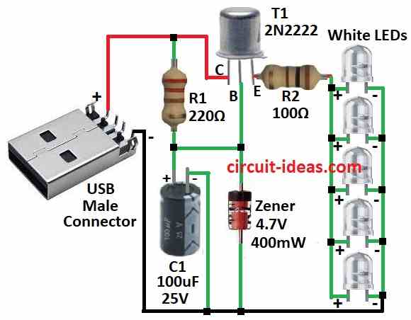
To begin with, make the table bright with this nice white LED lamp, as it run from USB port and is good when one take notes and looks for internet same time.
Here, USB give 5 volt and 100 milliamp which is enough to light the LED and circuit take power from USB using normal type-A plug.
A Zener diode keeps the power steady all the time and resistor R1 limits the current going to transistor T1 so the output current stays stable.
Moreover, one 4.7V Zener give steady 4.7 volt to LEDs which is good because white LED need at least 3.6V to work.
Resistor R2 controls the LED current to around 20 milliamps, so the LED does not break; but be careful when connecting the power wire to the USB and check the plus and minus sides.
Hence, if one want more light use something shiny like reflector behind the LEDs.
Formula:
Formula for LED in USB Reading Lamp Circuit:
Resistor RLED for LED current control:
We use ohms law to find value of resistor RLED for each LED.
RLED = (VUSB – VLED) / ILED
where:
- VUSB is the voltage from USB which is around 5 volt
- VLED is the voltage drop of LED for forward voltage
- ILED is the current we want for LED like 20 milliamp
Note:
Hence, with this formula and tips one can make USB reading lamp that work good with white LEDs; change resistor value if one wants more or less brightness or if the LED need different voltage.
Always test the circuit nicely to be sure it work right and if not, make small changes to get the best light.
How to Build:
To build a Simple USB Reading Lamp Circuit follow the below steps for connections:
Prepare USB Wire:
- First, cut the USB wire and remove outside cover to see power (red) and ground (black) wires.
Solder Parts:
- Next, put all parts like LEDs, Zener diode, transistor, resistors on the PCB, solder them as shown in circuit diagram and keep parts close so wires are not too long.
Connect Parts:
- After that, join all parts same like in circuit diagram and then check LED and Zener direction as they must be with correct side means polarity right.
Connect USB Wire:
- Then solder red wire (power) and black wire (ground) from USB to the circuit and be sure plus and minus is correct.
Test the Circuit:
- Now plug USB wire into computer or USB adapter and LEDs should turn ON with same brightness.
Be Safe:
- Cover the circuit well so no short circuit happens and use heat sink if needed while soldering so parts do not burn, also do not touch tip of solder iron.
- Work in place with fresh air and do not breathe smoke from coming solder.
Conclusion:
Overall, Simple USB Reading Lamp Circuit is easy and low cost project which gives small portable light using USB power.
Therefore, with easy parts like LED, resistor, one transistor and Zener diode one can make working lamp good for reading or extra light anywhere.
Finally, this project help one learn basic electronics and also make something useful one can really use.

Leave a Reply