Simple Radiation Sensor Circuit is like small spy for rays which one cannot see, it can smell different radiation like from light bulb, electromagnetic, or X-ray (ionizing one) etc.
Furthermore, this circuit have special sensor when radiation detects sensor feels it and send signal.
The circuit then uses that signal to modify things such as showing a number on the screen or even making the light brighter as more radiation comes in.
People also use this circuit in many things like smoke alarm, doctor machine and more.
Circuit Working:
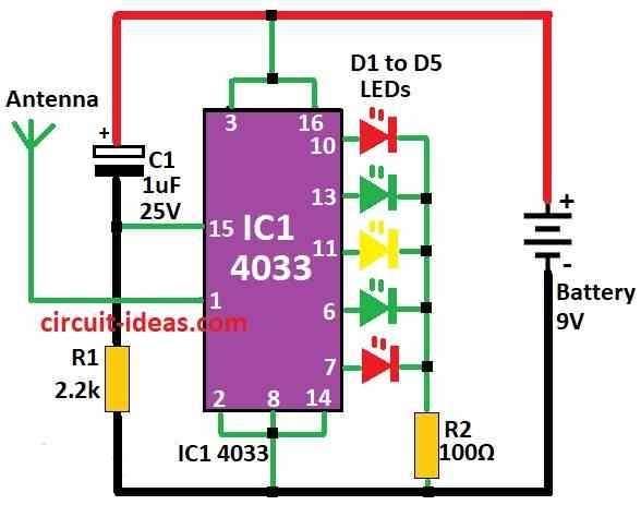
Parts List:
| Components | Values | Quantity |
|---|---|---|
| Resistors | 2.2k 1/4 watt | 1 |
| 100Ω 1/4 watt | 1 | |
| Capacitors | Electrolytic 1µF 25V | 1 |
| Semiconductors | IC 4033 | 1 |
| 5mm 20mA | 5 | |
| Antenna | 1 | |
| Battery 9V | 1 |
This is simple tool for checking how much radiation come from electric or electronic thing and when device make electromagnetic radiation the LEDs in circuit start running light pattern.
Also, it can catch radiation from computer or TV or even from 2 feet far or more and if light run fast it mean more radiation and if light run slow it mean less radiation.
Moreover, the IC 4033 is special chip which count from 0 to 9 and also light up 7 segment or LEDs with seven pins.
Here, pin 1 on IC is very sensitive it can feel electromagnetic energy even from far away and we use this to know how strong the radiation is.
However, pin 15, the reset pin, connects to C1 and R1 to reset the IC after a full count, so the IC can keep working until it detects no more signals.
Formulas:
For radiation sensor circuit we can use formula to find resistor for LED light:
RLED = (VCC − VLED) / ILED
where:
- VCC is battery voltage.
- VLED is how much voltage LED needs to glow.
- ILED is how much current connects with LED which is mostly 20mA for 5mm LED.
So use this formula to find resistor value for LED and just put the numbers one is having.
Note:
If we understand these numbers and how to use them one can make good radiation sensor using IC 4033 and we can also make it better by testing and changing parts if needed.
Antenna:
We can use small plastic wire for antenna and if one want it to look cool use telescopic antenna from old pocket radio.
Testing:
Put antenna near TV or old computer screen like CRT monitor, LEDs will turn ON one by one like chasing light.
Also, if light go fast more radiation and if it is slow then less radiation.
Then move the circuit away slowly and the light will become slower and will stop and this shows no more radiation in that place.
As a result, we can use this to check how much radiation is coming from electric devices and wires in our home.
How to Build:
To build a Simple Radiation Sensor Circuit follow the below mentioned steps:
- First, place the IC CD4033 as shown in the datasheet, then connect pin 1 as the clock input and pin 15 as the reset pin.
- Then 7 output pins connects to LED or 7 segment display.
- Join LEDs to output pins with resistors to stop too much current
- After that, connect antenna wire to pin 1 clock input of IC and this part will feel electromagnetic radiation.
- Now put one capacitor and one resistor in series from pin 15 reset to ground and this will make timing for reset so IC start again after one cycle; also it will help LEDs keep showing radiation level.
Power the Circuit:
- First, give power to IC and LEDs and use battery or power supply with right voltage for all parts.
Note:
- Be careful when working with electric things.
Conclusion:
To conclude, Simple Radiation Sensor Circuit is important electronic thing that help find and measure different kinds of radiation.
Also, it have many parts like sensor, amplifier, filter and display and these parts change based on what type of radiation we want to find.
Furthermore, many places use these circuits to protect people from radiation in hospital body-check machines, monitor radiation in the environment
Finally, the circuit provides useful information for research and safety.

Leave a Reply