Two simple mains phase detector circuit using the IC 4001 and IC 4060 are discussed in this article which are designed to detect the presence of mains AC 220V or 120V phase in the atmosphere.
It works without any physical contact with the mains and the antenna of the circuit detects the mains in the atmosphere.
Circuit Working (using IC 4001):
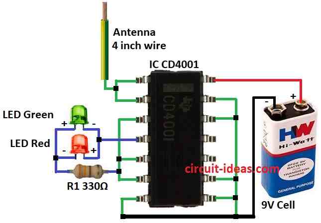
The IC 4001 is a quad 2 input NOR gate chip, through which we will understand the circuit working and how to build process mentioned below.
The inputs of any CMOS IC has a high impedances and therefore are highly sensitive to atmospheric RF interferences.
When the input of a CMOS IC detects AC mains interferences it is amplified across the relevant output of the specific gate.
In this circuit the inputs of CMOS IC CD4001 are used to sense mains AC 50Hz or 60Hz frequencies and indicate its presence through the relevant outputs using LEDs
Parts List:
Component Type | Value | Quantity |
---|---|---|
Resistors (1/4 watt) | 330Ω | 1 |
Semiconductors | IC CD4001 | 1 |
LEDs | Green 5mm 20mA | 1 |
Red 5mm 20mA | 1 | |
Antenna | 4 inch wire | 1 |
Power Source | 9V Cell battery | 1 |
How to Build:
To build a Simple Mains Phase Detector Circuit using IC CD4001 follow the below mentioned connection process:
- Connect pin 1 and 2 of IC CD4001 together through 4inch antenna wire.
- Connect pin 3, 5, and 6 together of IC CD4001.
- Connect LEDs green and red through pin 4 of IC CD4001.
- Connect resistor R1 through pin 3,5, and 6 of IC CD4001.
- Connect pin 7 of IC CD4001 to ground.
- Connect pin 8, 9, 12 and 13 of IC CD4001 together to ground.
- Connect pin 14 of IC CD4001 to positive supply of 9V cell.
- Connect negative supply of 9V cell to ground.
DC Electrical Characteristics for IC 4001
Symbol | Parameter | Conditions | Units | Min | Max | Min | Typ | Max | Min | Max |
---|---|---|---|---|---|---|---|---|---|---|
IDD | Quiescent Device Current | VDD=5V, VIN=VDD or VSS | μA | 1 | 0.004 | 1 | 7.5 | |||
VDD=10V, VIN=VDD or VSS | μA | 2 | 0.005 | 2 | 15 | |||||
VDD=15V | μA | 4 | 0.006 | 4 | 30 | |||||
VOL | Low Level Output Voltage | VDD=5V | V | 0.05 | 0 | 0.05 | 0.05 | |||
VDD=10V | V | 0.05 | 0 | 0.05 | 0.05 | |||||
VDD=15V | V | 0.05 | 0 | 0.05 | 0.05 | |||||
VOH | High Level Output Voltage | VDD=15V | V | 4.95 | 5 | 4.95 | ||||
VDD=10V | VDD=10V | V | 9.95 | 10 | 9.95 | |||||
VDD=5V | VDD=5V | V | 14.95 | 15 | 14.95 | |||||
VIL | Low Level Input Voltage | VDD=5V, VO=4.5V | V | 1.5 | 2 | 1.5 | 1.5 | |||
VDD=10V, VO=9.0V | V | 3.0 | 4 | 3.0 | 3.0 | |||||
VDD=15V, VO=13.5V | V | 4.0 | 6 | 4.0 | 4.0 | |||||
VIH | High Level Input Voltage | VDD=5V, VO=0.5V | V | 3.5 | 3.5 | 3 | 3.5 | |||
VDD=10V | VDD=10V | V | 7.0 | 7.0 | 6 | 7.0 | ||||
VDD=15V, VO=1.5V | V | 11.0 | 11.0 | 9 | 11.0 | |||||
IOL | Low Level Output Current | VDD=5V, VO=0.4V | mA | 0.52 | 0.44 | 0.88 | 0.36 | |||
VDD=10V | VDD=10V | mA | 1.3 | 1.1 | 2.25 | 0.9 | ||||
VDD=15V | VDD=15V | mA | 3.6 | 3.0 | 8.8 | 2.4 | ||||
IOH | High Level Output Current | VDD=5V, VO=4.6V | mA | -0.52 | -0.44 | -0.88 | -0.36 | |||
VDD=10V | VDD=10V | mA | -1.3 | -1.1 | -2.25 | -0.9 | ||||
VDD=15V | VDD=15V | mA | -3. |
Circuit Working (using IC 4060):
Parts List:
Component Type | Value | Quantity |
---|---|---|
Resistor (1/4 watt) | 1k | 1 |
Semiconductors | IC 4060 | 1 |
LED | Any 5mm 20mA | 1 |
Antenna | – | 1 |
Power Source | 9V Battery | 1 |
A CMOS IC reacts when its input senses AC main interference such as frequencies of 50Hz or 60Hz.
After being detected the signal is amplified and arrives at the appropriate output of the designated gate inside the IC.
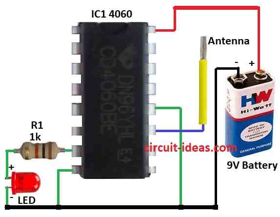
The CMOS IC 4060 is utilized in the particular circuit that was described.
The ICs input pin 11 is wired to detect the presence of 50Hz or 60Hz mains AC frequencies.
An LED is turned on via a 1k resistor if the output at pin 7 of the integrated circuit detects AC mains interference.
The LED acts as a signal to indicate the presence of AC mains interference.
Applications requiring the detection of particular frequencies or the monitoring of the existence of AC mains electricity may find this circuit beneficial.
How to Build:
To build a Mains Phase Detector Circuit using IC 4060 its connections process is mentioned below:
- Connect pin 7 of IC 4060 to ground through resistor R1 and LED.
- Connect pin 8 of IC 4060 to ground.
- Connect pin 11 of IC 4060 to a antenna.
- Connect pin 12 of IC 4060 to ground.
- Connect pin 16 of IC 4060 to positive supply of 9V battery.
- Connect negative supply of 9V battery to ground.
Static Electrical Characteristic for IC 4060
CHARACTERISTIC | CONDITIONS | +25°C |
---|---|---|
Quiescent Device Current, IDD Max | VDD=5V, VIN=VDD or VSS | 0.04 µA |
VDD=10V, VIN=VDD or VSS | 0.04 µA | |
VDD=15V | 0.04 µA | |
Output Low (Sink) Current, IOL Min | VDD=5V, VO=0.4V | 0.36 mA |
VDD=10V | 0.9 mA | |
VDD=15V | 2.4 mA | |
Output High (Source) Current, IOH Min | VDD=5V, VO=4.6V | -0.36 mA |
VDD=10V | -0.9 mA | |
VDD=15V | -2.4 mA | |
Output Voltage: Low-Level, VOL Max | VDD=5V | 0.05 V |
VDD=10V | 0.05 V | |
VDD=15V | 0.05 V | |
Output Voltage: High-Level, VOH Min | VDD=5V | 4.95 V |
VDD=10V | 9.95 V | |
VDD=15V | 14.95 V | |
Input Low Voltage, VIL Max | VDD=5V, VO=4.5V | 1.5 V |
VDD=10V, VO=9.0V | 3.0 V | |
VDD=15V, VO=13.5V | 4.0 V | |
Input High Voltage, VIH Min | VDD=5V, VO=0.5V | 3.5 V |
VDD=10V | 7.0 V | |
VDD=15V, VO=1.5V | 11.0 V | |
Input Current, IIN Max | – | ±100 µA |
Safety Measures:
- Always double check component ratings to ensure they are suitable for the voltage you are working with.
- Use proper personal protective equipment PPE like insulated gloves and work on a non conductive surface.
- If unsure about any aspect, err on the side of caution and seek professional help.
Conclusion:
A dependable and affordable method for identifying phase changes in mains AC signals is to use CMOS integrated circuits in a mains phase detector circuit.
Power management and synchronization systems among other applications, can benefit from the circuits high precision and low power consumption, which are achieved through the use of CMOS integrated circuits ICs.
It is a well liked option for determining phase angles in mains power systems due to its ease of use and efficiency.
References:
A Power And Delay Efficient Circuit For Cmos Phase Detector And Phase Frequency Detector
Leave a Reply