A Simple Solenoid Driver Circuit is a setup to control solenoid using low voltage signal; solenoids are like magnets and they change electric power into movement.
Furthermore, they need more voltage than small digital parts like microcontrollers can give, also the driver works like a switch and it lets small signal turn big current ON and OFF for solenoid.
Circuit Working:
Parts List:
| Components | Values | Quantity |
|---|---|---|
| Resistors | 1k 1/4 watt | 1 |
| 10k 1/4 watt | 1 | |
| Capacitors | Ceramic 1nF | 1 |
| Semiconductors | IC 7812 | 1 |
| MOSFET IRF540 | 1 | |
| Diode 1N4007 | 1 | |
| ON/OFF switch | 1 | |
| 12V Solenoid | 1 |
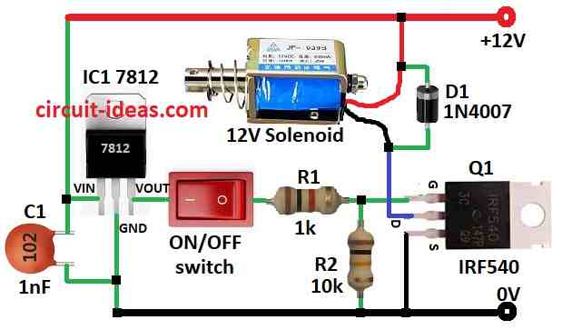
This article explains a circuit that uses a switch and low voltage to control a solenoid and the full design appears in the image above and we can also build it on a small board because it is not difficult to construct.
In this circuit, the solenoid operates when we apply 12V and turns OFF when we remove power; the circuit uses a MOSFET, a special switch that we control with low voltage, to turn the solenoid ON and OFF.
Important part here is MOSFET IRF540 and some things to check when choosing MOSFET:
- It must turn ON at low voltage and this one needs 4V and circuit gives 5V so it works and it must handle enough current and this one can take 10A and whereas solenoid needs only 1.2A.
- Always better to pick MOSFET that handles more current than needed.
- When ON, it should have low resistance so solenoid gets full voltage whereas this one has only 0.077 ohm which is good.
If using other solenoid then check its datasheet.
The 12V supply becomes 5V using IC1 7812 regulator.
When we press the switch, 5V reaches the MOSFET gate pin through the 1k resistor R1 and when we do not press the switch, the 10k resistor R2 pulls the gate pin to ground, so the MOSFET stays OFF.
Also, we add a diode in reverse (anti-parallel) to prevent back current from the solenoid coil from flowing into the power line.
Formulas:
Lets see main formula and things to think about when making solenoid driver circuit:
Solenoid current (Isol):
We need to know how much current solenoid pulls from power.
Isol = Vout / Rload
where:
- Vout is 12V from IC 7812 output
- Rload is solenoids resistance
Check if voltage and current ratings of all parts match our solenoid and use case, if solenoid needs high current then test circuit well.
Ensure MOSFET can handle heat and change parts and values as needed for our solenoid.
How to Build:
To build a Simple Solenoid Driver Circuit follow the below mentioned steps for assembling.
- First, gather all parts shown in circuit diagram.
- After that, connect MOSFET Q1 gate pin to point between R1 and R2, connect drain pin of Q1 to one wire of 12V solenoid also connect other solenoid wire to +12V supply and then connect source pin of Q1 to ground (0V).
- Now connect Vin pin of IC1 7812 between C1 capacitor and +12V supply, connect GND pin of IC1 to 0V negative supply and then connect Vout pin of IC1 to R1 resistor through ON/OFF switch.
- Also, solenoid wires go between Q1 drain and +12V supply and then connect diode D1 in parallel with solenoid wires for reverse direction.
Safety Tips:
- Solenoids can use high current/voltage so we should use right rated parts, so do not use solenoids near fire or explosion risk because its switching can spark.
Conclusion:
To conclude, with voltage regulator and MOSFET switch this Simple Solenoid Driver Circuit lets us turn ON big solenoid using small low voltage switch.
Moreover, this circuit is easy to make but we should just take proper care while making it.
Leave a Reply