Stable 5V power needed for many electronics like sensors, microcontrollers and digital parts.
The LM7805 voltage regulator IC forms a 12V to 5V converter, also this highly useful circuit converts 230V AC to 5V DC, ensuring reliable and stable device operation.
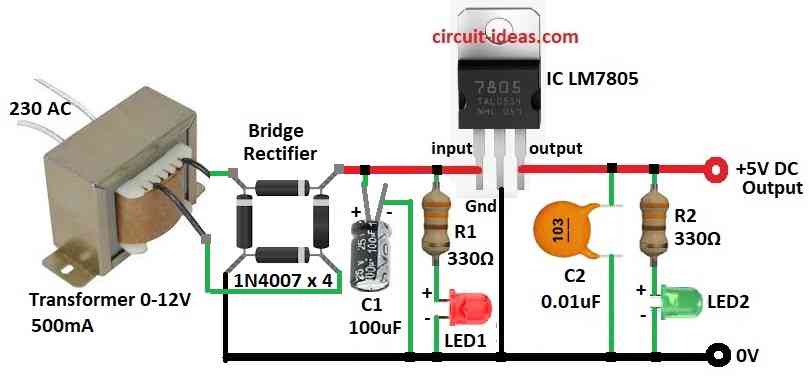
Also, main parts of the circuit are transformer, bridge rectifier, filter capacitors, resistors and LEDs.
Here, Transformer drops 230V AC to 12V AC, bridge rectifier makes AC to DC and capacitors of 100µF/25V and 0.01µF smooth the DC and also LM7805 makes this DC steady 5V for device use.
Two 330Ω resistors used for red and green LEDs to stop extra current and show power status.
This simple circuit work well and are good for many electronic projects.
So next we will see 3 Ways to Build a 12V to 5V Converter Circuit using IC LM7805 which will explain working, formulas and how to make process.
Circuit Working:
Parts List for all three circuit diagram:
| Components | Values | Quantity |
|---|---|---|
| Resistors | 330Ω 1/4 watt | 2 |
| 1k 1/4 watt | 2 | |
| Capacitors | Electrolytic 100µF/25V,10µF 16V, 10µF 16V | 1 each |
| Ceramic 0.01µF | 1 | |
| Semiconductors | IC LM7805 | 1 |
| Transformer 230V to 0-12V AC | 1 | |
| Bridge Rectifier Module 1N4007 | 4 | |
| LED Red 5mm 20mA | 1 | |
| LED Green 5mm 20mA | 1 |
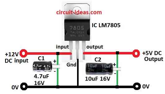
To begin with, IC 7805 comes in many shapes and can use on prototype board or PCB easily.
Now we make 5V DC regulator from start, so 7805 is good choice as it gives 5V from 12V to 35V DC input and max current is 1.5A and it has 3 pins: input, ground and output.
Need to add right capacitors for stable input and output, also heat sink often needed to remove extra heat.
All 3 circuits do the same job, first circuit connect between 12V DC supply and 5V device, second circuit shows when voltage is present and third circuit shows AC to DC 5V regulated power supply.
We can also use as stand alone 5V source.
Formulas:
Below are formulas for 3 types of LM7805 circuits.
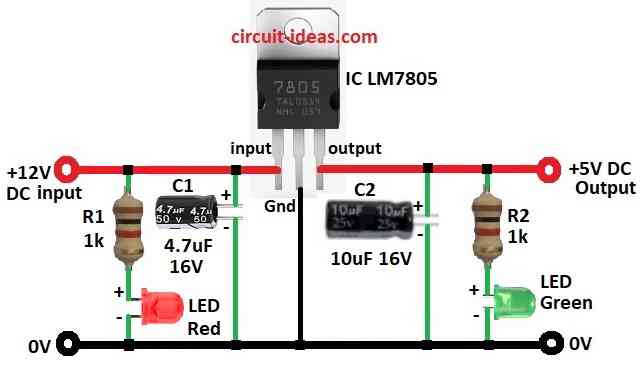
LM7805 Circuit with LEDs:
To find LED current use ohms law.
Red LED drop (Vf) = 2V and Green LED drop = 2.2V.
Formulas:
Red LED: IR1 = (Vin − Vf) / R1
Green LED: IR2 = (Vout − Vf) / R2
Each part and formula helps with voltage control, less noise, LED shows status and better circuit stability, also we must know these things to build good working circuits.
How to Build:
3 Ways to Build a 12V to 5V Converter Circuit using IC LM7805 follow the below mentioned steps:
Connect IC 7805:
- First, input pin to +12V DC, GND pin to GND and then output pin to +5V DC
Add capacitors:
- Then C1 4.7µF goes from +12V to GND and then C2 10µF goes from +5V to GND
Second Circuit:
- Same as first circuit
Add LEDs and resistors:
- After that, connect R1 1kΩ + Red LED in series from +12V to GND and then connect R2 1kΩ + Green LED in series from +5V to GND
Third Circuit:
- Now connect R1 330Ω + Red LED1 in series from +12V to GND and then connect R2 330Ω + Green LED2 in series from +5V to GND
Add capacitors:
- Next add C1 100µF +12V to GND and then add C2 0.01µF +5V to GND
Connect bridge rectifier:
- Now Positive terminal goes to 7805 input, negative terminal goes to GND and then AC terminals goes to 12V output from transformer
Conclusion:
To conclude, this post for 3 Ways to Build a 12V to 5V Converter Circuit using IC LM7805 fits many PCB types and are good for making 5V DC regulator.
Moreover, it works from 12V to 35V input and gives stable 5V output, also it is useful for powering devices, showing voltage or giving stand alone 5V source.
So using heat sinks and right capacitors makes it more stable and reliable.
Leave a Reply