Building an LDR Comparator Circuit using IC LM339 is useful and important in many electronic jobs like sensing and control, also using LDR, resistors, LED and LM339 IC we can make a simple circuit to check light level and show light change.
LDR works like light sensor and its resistance changes when light changes and using preset and fixed resistor we can make voltage divider and this voltage changes when light changes.
Then IC LM339 compares this voltage with a fixed reference voltage from resistor and if light goes above set level then comparator sends signal and LED turns ON to show light change.
Hence, this circuit compares voltage, senses input, and generates an output signal; also it is easy to build, useful for learning, and applicable in both small light-based tools and larger systems.
Also, IC LM339 with LDR is great example of simple parts doing useful work.
Circuit Working:
Parts List:
| Components | Values | Quantity |
|---|---|---|
| Resistors | 33k 1/4 watt | 1 |
| 330Ω 1/4 watt | 1 | |
| Preset 10k | 1 | |
| LDR | 1 | |
| Semiconductors | IC LM339 | 1 |
| LED 5mm 20mA | 1 |
The LM339 is a quad comparator and this LDR circuit uses only one of its comparators, also it operates on a 5V DC power supply.
Further, LDR is light sensor and its resistance changes with light, more light means less resistance.
Then resistor R1 makes voltage divider and LDR connects to pin 4.
When light increases the LDR resistance drops and voltage at pin 4 goes up and pin 3 gives low output.
After that pin 5 has variable resistor VR1 and if VR1 is low then voltage at pin 5 goes high, so to get good output in low light then pin 4 inverting input must stay below pin 5 voltage.
When LDR sees more light then resistance drops and output voltage increases.
Now comparator changes output when pin 4 inverting voltage crosses pin 5 non-inverting voltage and in dark the LDR resistance is high and LED turns ON.
Formulas:
Main formulas for LDR comparator circuit using LM339:
1. Voltage Divider for pin 4 inverting input:
Vpin4 = (RLDR / (RLDR + R1)) × VCC
where,
- Vpin4 is the voltage at pin 4
- RLDR is the LDR resistance which changes with light
- R1 is the fixed resistor with 33k
- VCC is the 5V supply
2. Voltage at pin 5 for non-inverting input:
Vpin5 = (R2 / (R1 + R2)) × VCC
where,
- R2 is the VR1 for variable resistor setting
- VCC is the 5V supply
3. LED Current:
ILED = (VCC − VLED) / R2
where,
- VLED is the LED forward voltage to about 2V
- R2 is the resistor to limit current for 330Ω
These formulas help to set correct voltage and current in the circuit and we can adjust VR1 to change how sensitive the circuit is to light.
How to Build:
For Building an LDR Comparator Circuit using IC LM339 follow the below mentioned steps for connections:
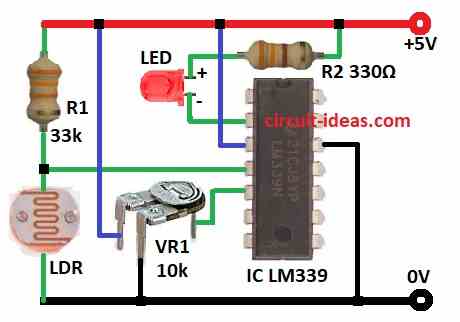
- First, connect pin 2 of LM339 to +5V through LED and 330Ω R2 resistor.
- Next, connect pin 3 to +5V.
- After that, connect pin 4 to the point where R1 33k and LDR join and other end of LDR goes to GND.
- Now connect pin 5 to middle pin of VR1, one side of VR1 goes to +5V and other side to GND.
- Finally, connect pin 12 of LM339 to GND.
Conclusion:
Overall, Building an LDR Comparator Circuit using IC LM339 shows how to compare voltage and detect light, it checks light level using LDR and preset resistor and gives output like LED ON/OFF.
We can easily modify the circuit for other projects like relays or buzzers, it also helps you learn the basics and supports development of larger sensing circuits later.
.
Leave a Reply