Simple DIY Battery Charger Circuit using Center Tap Transformer is a useful device, it fills power in rechargeable battery.
Furthermore, this article show how to make easy DIY charger using center tap transformer which is good for charging lead acid battery; also it can charge any 12V battery and even a car battery.
Circuit is simple and works well and it uses basic parts and can charge 6V and 12V batteries and it is good for hobby people who wants to try small project.
Circuit Working:
Parts List:
| Components | Values | Quantity |
|---|---|---|
| Capacitor | Electrolytic 2200µF 25V | 1 |
| Semiconductors | Center Tap Transformer: steps down the mains voltage 230V AC to 12-0-12V 5A | 1 |
| Diodes 1N4007 | 2 | |
| Ammeter 0-5A | 1 | |
| Rechargeable Battery battery to charge | 1 |
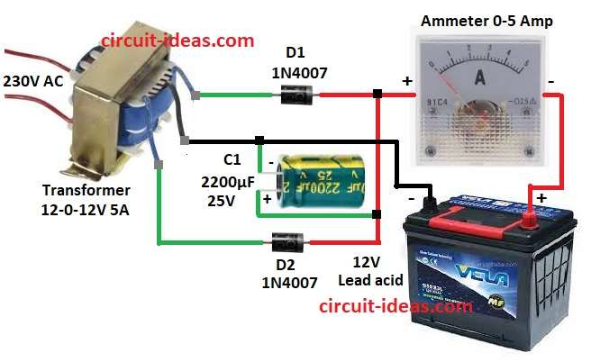
To begin with, see the circuit diagram above to understand how it work.
This circuit has main parts like center tap transformer, diodes, capacitor and ammeter and all parts are important for charging.
Further, transformer change high voltage to safe 12V AC.
Diodes D1 and D2 make full wave rectifier and it turn AC to bumpy DC and capacitor C1 smooth the DC and makes it steady.
Hence, this smooth DC goes to battery for charging and then ammeter shows how much current go to battery which helps to watch charging.
Note: Connect charger correct way like battery positive to supply positive and battery negative to supply negative.
Formulas with Calculations:
Formulas and Calculations for Simple DIY Battery Charger:
Transformer:
Secondary voltage = 12V RMS
Peak voltage = 12 × 1.414 = 16.97V
Capacitor:
Load current = 5A
Ripple voltage (∆V) = 2V (assume)
Time (t) = 1 / (2 × 50) = 0.01s for 50Hz
Formula:
C = (I × t) / ∆V
C = (5 × 0.01) / 2 = 0.025F = 25000µF approx
We can use 2200µF also, as ripple will be more but still okay for simple use.
Diodes:
Peak inverse voltage (PIV) = 2 × 16.97 = 33.94V
So diode 1N4007 can handle 1000V which is good.
How to Build:
To build a Simple Battery Charger Circuit using Center Tap Transformer following steps will help for DIY project and connections:
- First, take all parts shown in circuit diagram.
- Next, connect top outer wire of transformer to anode of D1 and cathode of D1 to positive of capacitor C1.
- Then connect center tap wire of transformer to negative of capacitor C1 and connect positive of C1 to both cathodes of D1 and D2.
- After that, connect positive of C1 to positive of ammeter and connect negative of ammeter to positive of 12V battery.
- Now connect negative of C1 to negative of 12V battery.
Conclusion:
Overall, this Simple DIY Battery Charger Circuit using Center Tap Transformer is good to charge lead acid batteries; also it is easy to make and its parts are easy to find.
Hence, for better safety we can add voltage control and overcharge protection.
Leave a Reply