
This AC Lamp Flasher using an SCR operates directly from the 230V AC mains, also it offers a simple, low cost design, making it suitable for decorative lighting, warning lamps and festival lighting.
The circuit uses an SCR for switching and an RC timing network to control the flashing operation; as a result, the lamp turns ON and OFF automatically, and the resistor and capacitor values determine the flashing speed.
Circuit Working:
Parts List:
| Components | Values | Quantity |
|---|---|---|
| Resistors (All resistors are 1/4 watt) | 2.7k, 22k | 1 each |
| 1k | 2 | |
| Potentiometer 100k | 1 | |
| Capacitor | Electrolytic 100uF 25V | 1 |
| Diode 1N4007 | 3 | |
| SCR BT151 | 1 | |
| AC Load 230V AC Bulb 40W to 200W Incandescent Lamp | 1 | |
| AC Input 110V or 230V AC | 1 |
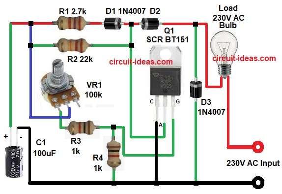
First, this circuit operates directly from the 230V AC mains, so we should take proper safety precautions before testing it, also when we apply the AC supply, capacitor C1 starts charging through R1, R2 and diode D2.
Meanwhile, SCR is in OFF condition and so the AC load (bulb) is OFF and as time passes the capacitor voltage increases slowly.
When capacitor voltage reaches gate trigger voltage of SCR then current flows through R3 into the gate terminal and therefore, SCR turns ON.
Now once SCR turns ON it allows current from AC input to pass through load and as a result the bulb glows.
However, during negative half cycle of AC, SCR turns OFF because SCR works only in forward direction and then again capacitor starts charging in next cycle, thus, the process repeats continuously and so the bulb keeps flashing.
Diodes D1 and D2 control the charging and discharging paths, while diode D3 protects the SCR from reverse voltage and voltage spikes, also together, these components produce controlled flashing.
Formula with Calculation:
Time period of flashing mainly depends on R and C values.
Basic RC time formula: T = R × C
where,
- T is the time in seconds
- R is the resistance in ohms
- C is the capacitance in farads
Calculation as per circuit:
- R (total timing resistance VR1) is 100k ohm
- C1 is 100 microfarad = 100 × 10^-6 farad
- T = 100000 × 0.0001 T = 10 seconds
So lamp will approximately flash every 10 seconds and if we reduce R or C value the flashing becomes faster and if we increase R or C value then flashing becomes slower.
SCR Gate Current Formula:
Gate current formula:
Ig = (Vc – Vg) / R3
Lets take:
- Vc is 10V
- Vg is 0.7V
- R3 is 1k
Ig = (10 – 0.7) / 1000
Ig = 9.3 mA
BT151 typical gate trigger current is from 5 to 15 mA, so 9 mA current is safe for our circuit.
How to Build:
To build a AC Lamp Flasher Circuit using SCR follow the below connection steps:
- Start the circuit by collecting all the circuit parts.
- Next, SCR anode pin connect to to the junction of resistor R2 and diode D1 and D2 network and cathode pin connect to circuit neutral line.
- Then gate pin connect to junction of R3 and R4 timing network.
- Also, diode D3 connect across SCR for protection.
- Now capacitor C1 positive terminal connects to resistor network side and negative terminal connects to AC neutral supply.
- Further, VR1 center pin connected to one end of resistor R1 and R2, VR1 bottom pin connected to one end of resistor R3.
- After that, AC Load one side connects to AC input phase and other side connects to SCR anode path.
Safety Tips:
- This circuit works on high AC voltage of 230V or 110V, so it is dangerous.
- Always use proper insulation.
- Do not touch when power is ON.
- Use fuse for protection.
Conclusion:
To conclude, this AC Lamp Flasher Circuit using SCR is simple and effective, as it uses few components and it works directly from mains supply.
Therefore, this circuit is suitable for home decoration and signal lamp applications, we can also adjust the flashing speed easily by changing the value of the resistor or capacitor.
So beginners can experiment and learn about SCR working and finally, this project helps to understand RC timing and thyristor switching clearly in practical way.