• Skip to primary navigation
  • Skip to main content
  • Skip to primary sidebar

Circuit Ideas for You

Get free circuit ideas online.

  • Home
  • Privacy Policy
  • About
Home » Arduino Bluetooth Appliance Controller Circuit

Arduino Bluetooth Appliance Controller Circuit

Last updated on 14 November 2025 by Admin-Lavi Leave a Comment

This project shows how to control a home appliance with Arduino.

Bluetooth module HC05 sends command from mobile.

Relay switches the AC load like bulb or fan.

Arduino Bluetooth Appliance Controller Circuit is simple and safe when wired correctly.

Good for beginners who want home automation.

Arduino Coding:

#include <SoftwareSerial.h>
SoftwareSerial BT(10, 11);

int relay = 7;

void setup() {
pinMode(relay, OUTPUT);
digitalWrite(relay, LOW);
BT.begin(9600);
}

void loop() {
if (BT.available()) {
char c = BT.read();
if (c == '1') {
digitalWrite(relay, HIGH);
}
if (c == '0') {
digitalWrite(relay, LOW);
}
}
}

Code Explanation:

  • SoftwareSerial makes pin 10 and 11 act like RX and TX.
  • Relay pin is set as output.
  • Bluetooth sends characters like 1 or 0.
  • When Arduino gets 1 it turns ON relay.
  • When Arduino gets 0 it turns OFF relay.
  • Relay controls AC load.

Circuit Working:

Arduino Bluetooth Appliance Controller Circuit Diagram

Parts List:

ItemQuantity
Arduino UNO1
HC-05 Bluetooth Module1
Relay Module 5V1
Bulb 220V1
Mobile Phone1
220V AC Supply1
USB Cable1

HC05 sends signals to Arduino.

Arduino reads TX signal and decides ON or OFF.

Relay module gets 5 volt from Arduino.

Relay works like a switch.

Phase wire from AC goes into relay.

Relay breaks or connects phase wire.

Bulb turns ON when relay closes.

Bulb turns OFF when relay opens.

How To build:

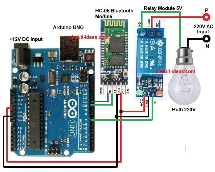
To build a Arduino Bluetooth Appliance Controller Circuit follow the below steps for connection:

  • Take all the parts as shown in circuit diagram.
  • HC05 VCC pin connect to Arduino 5V.
  • HC05 GND connect to to Arduino GND.
  • HC05 TX pin connect to Arduino pin 10.
  • HC05 RX pin connect to Arduino pin 11 through a level shifter or voltage divider.
  • Relay module VCC pin goes to Arduino 5V.
  • Relay GND pin go to Arduino GND.
  • Relay IN pin go to Arduino pin 7.
  • AC phase wire from mains goes to relay input terminal.
  • Relay output terminal goes to bulb phase.
  • Neutral from mains goes directly to bulb neutral.

Conclusion:

This Arduino Bluetooth Appliance Controller Circuit is easy for beginners.

Arduino and Bluetooth give wireless control.

Relay lets us automate any AC appliance.

Good base project for bigger smart home systems.

References:

Creating a bluetooth controller

Filed Under: Arduino Projects, IoT projects

About Admin-Lavi

Lavi is a B.Tech electronics engineer with a passion for designing new electronic circuits. Do you have questions regarding the circuit diagrams presented on this blog? Feel free to comment and solve your queries with quick replies

Previous Post: « Arduino Line Follower Robot Circuit

Reader Interactions

Leave a Reply Cancel reply

Your email address will not be published. Required fields are marked *

Primary Sidebar


Categories

  • Alarm Circuits (39)
  • Amplifier Circuits (67)
  • Arduino Projects (72)
  • Audio Circuits (101)
  • Automobile Circuits (19)
  • Battery Charger Circuits (54)
  • Free Energy (13)
  • Heater and Temperature Controllers (12)
  • High Voltage (1)
  • Indicator Circuits (44)
  • Inverter Circuits (16)
  • IoT projects (1)
  • LDR Circuits (24)
  • LED and Lamps (134)
  • Meters and Testers (30)
  • Motor Controllers (19)
  • Oscillator Circuits (35)
  • Power Supply Circuits (94)
  • Remote Control Circuits (10)
  • Security and Protection (26)
  • Sensors and Detectors (107)
  • Solar Circuits (23)
  • Timer Circuits (33)
  • Transistor Circuits (68)
  • Transmitter Circuit (16)
  • Tutorials (8)
  • Water Level Controller (4)

Recent Posts

  • Arduino Bluetooth Appliance Controller Circuit
  • Arduino Line Follower Robot Circuit
  • Simple PIR Motion Detector Circuit
  • Simple Thermistor Based Fire Alarm Circuit
  • Fire Alarm Circuit using IC LM358

Recent Comments

  1. Henrik Arboe Jensen on Adjustable Voltage, Current Power Supply Circuit using Transistor 2N3055
  2. Admin-Lavi on FM Transmitter Circuit (100 meters range)
  3. DEVINDER SINGH on FM Transmitter Circuit (100 meters range)
  4. Admin-Lavi on Constant Voltage, Constant Current Battery Charger Circuit
  5. Bill on Constant Voltage, Constant Current Battery Charger Circuit

Copyright © 2025 | New Circuit Ideas