An Arduino with a Non-Contact Liquid Sensor Circuit detects water or other liquids without touching them; therefore, it functions as a contactless sensor.
Also, it works on capacitance change near container wall and sensor sense water inside plastic or glass without direct contact.
Moreover, it is safe, easy and clean project one should give it a try for.
Arduino Code:
int sensorPin = 8;
int sensorValue = 0;

void setup() {
pinMode(sensorPin, INPUT);
Serial.begin(9600);
}

void loop() {
sensorValue = digitalRead(sensorPin);
if(sensorValue == HIGH) {
Serial.println("Liquid Detected");
} else {
Serial.println("No Liquid");
}
delay(500);
}
Code Explanation:
- Sensor pin set as input.
- Arduino read signal using digitalRead.
- If sensor output HIGH then it means liquid is present.
- Serial monitor show “Liquid Detected”.
- If LOW then “No Liquid” shown.
- Delay added for slow print.
Circuit Working:
Parts List:
| Components | Quantity |
|---|---|
| Arduino UNO | 1 |
| XKC-Y26-V Sensor | 1 |
| Multimeter | 1 |
| Container like Plastic or Glass | 1 |
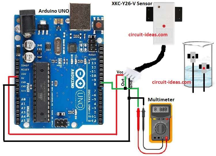
- Put plastic or glass water container on table as per circuit diagram.
- Clean outer wall where sensor will sit.
- Place XKC-Y26-V sensor on outside wall with flat side near water line.
- Fix sensor with tape or clip but not too hard.
- Connect Red wire to Arduino 5V.
- Black wire to Arduino GND.
- Green wire to Arduino pin D8 or multimeter +
- If using a multimeter then black probe to GND and red probe to signal wire.
- Start with empty container.
- Sensor will see air only.
- Output will be LOW to 0V.
- Multimeter will show 0V.
- Arduino will read LOW.
- No buzzer or pump.
- Pour water slowly.
- Water rise to sensor level.
- When water is near sensor then dielectric will change.
- Capacitance increase inside sensor.
- Circuit detects the change.
- Output will go HIGH to 5V.
- Multimeter will show 5V.
- Arduino will read HIGH.
- Now buzzer, LED, pump can turn ON.
- If water keep rising then output will stay HIGH.
- Sensor changes only when level crosses.
- When water goes down then dielectric back to air.
- Capacitance will drop.
- Output will go back to LOW with 0V.
- Multimeter will show 0V.
- Arduino will read LOW.
- Pump or alarm will stop.
Formula:
Sensor work on capacitance formula.
C = ε × A / d
where,
- C is capacitance
- ε is permittivity of material
- A is plate area
- d is distance between sensor and liquid.
When liquid level rises effective permittivity ε increase, so capacitance change and then sensor detect this change and give digital output.
How to Build:
To build a Arduino with Non Contact Liquid Sensor Circuit follow the below connections steps:
- First, gather all the components as shown in circuit diagram
- Next, connect the sensors red wire to the Arduinos 5V pin and the black wire to the GND pin.
- Then, connect the sensors green signal output wire to Arduino digital pin D8.
- Now multimeter connect its black probe to GN and red probe to sensor signal output of sensor
Conclusion:
To conclude, Arduino with Non Contact Liquid Sensor Circuit is very simple, it is safe because no direct touch with liquid.
Furthermore, it uses capacitance principle and with Arduino we can detect level and make alarms, motor control or auto cut off.
Also, it is cheap, useful and easy for projects.
Leave a Reply