Music is not only meant to be heard; it can also be seen and with the MSGEQ7 chip, we can make music dance through lights.
IC MSGEQ7 is an integrated circuit designed for audio spectrum analysis and it divides an audio signal into seven frequency bands and produces an output voltage proportional to the signal level in each band.
A microcontroller, such as an Arduino, ESP32, or STM32, can read these output voltages for further processing.
Moreover, circuit is good for making music visualizer, LED lights dancing and audio meters.
Simple vertical bar diagram (7 bands, 8 LEDs per band).
Each column = one frequency band (7 columns).
Top = high level, bottom = low level.
Band7  █ █ █ █ █ █ █ █
Band6  █ █ █ █ █ █ █ ░
Band5  █ █ █ █ █ ░ ░ ░
Band4  █ █ █ █ ░ ░ ░ ░
Band3  █ █ █ ░ ░ ░ ░ ░
Band2  █ █ ░ ░ ░ ░ ░ ░
Band1  █ ░ ░ ░ ░ ░ ░ ░
        1 2 3 4 5 6 7   (columns = bands)
Legend: █ = LED on, ░ = LED off.
We can change 8 to any number of LEDs per column.
Simple horizontal bar diagram (7 rows, variable length).
Each row = one band and Length = level.
Band7: ████████
Band6: ██████
Band5: ████
Band4: ███
Band3: ██
Band2: █
Band1: █
Compact 7-bar single-row (good for LED strip):
One row, 7 groups and each group has 3 LEDs.
[ B1: ▓▓ ] [ B2: ▓▓▓ ] [ B3: ▓ ] [ B4: ▓▓▓▓ ] [ B5: ▓▓ ] [ B6: ▓▓▓ ] [ B7: ▓▓▓▓ ]Circuit Working:
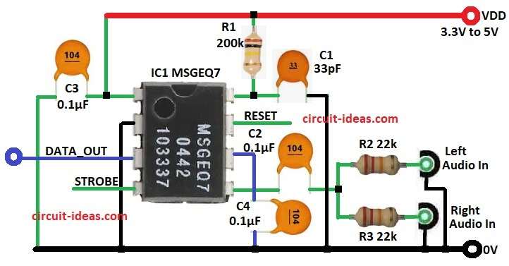
Parts List:
| Components | Values | Quantity |
|---|---|---|
| Resistors | 200k 1/4 watt | 1 |
| 22k 1/4 watt | 2 | |
| Capacitors | 33pF | 1 |
| 0.1µF | 3 | |
| Semiconductors | IC MSGEQ7 | 1 |
To begin with, the circuit diagram above shows a single MSGEQ7 configuration with a mono input, also the audio signal passes through a resistor and a capacitor before entering the chip.
Chip separates into 7 bands and output pin gives DC voltage for each band.
Then RESET pin set back to start and STROBE pin move to next band and also DATA_OUT pin send band level.
Mix the left and right channels with two 22k resistors and couple them through the same capacitor to the input pin.
Thus, both channels combine into a mono signal before entering the chip.
Finally, chip then works the same way.
How to Build:
To build a Audio Spectrum Analyzer Circuit using IC MSGEQ7 follow the below steps:
- First, gather all the parts as shown in circuit diagram
- Next, pin 1 VDD of IC MSGEQ7connect to 3.3V or 5V
- After that, pin 2 GND connect 0V
- Now pin 3 DATA_OUT goes to microcontroller ADC
- Also, pin 4 STROBE control by microcontroller
- Then pin 5 AUDIO_IN go to audio IN left and Audio IN right through resistor R2 and R3 and capacitor C2
- Further, pin 6 GND go with capacitor C4 to filter noise
- Finally, pin 7 RESET control by microcontroller and pin 8 Rbias connect resistor R1 to VDD and capacitor C1 to ground.
Conclusion:
Overall, the MSGEQ7 is an easy to use chip for a spectrum analyzer, requires only a few components and works with both mono and stereo inputs.
Also, output is easy to read by Arduino or any microcontroller and circuit is good for DIY music visualizer projects.
Leave a Reply