
This project explains about a complete Automatic PIR Motion Sensor Light Circuit, it is very useful for home and outdoor lighting, because the circuit uses a PIR sensor.
Whenever the PIR sensor detects motion, it turns the light ON automatically and after a preset delay, it turns the light OFF, saving power and reducing human effort.
Circuit Working:
Parts List:
| Components | Values | Quantity |
|---|---|---|
| Resistors (All resistors are 1/4 watt) | 1k | 2 |
| 4.7k | 1 | |
| 1M | 1 | |
| 100k | 1 | |
| Capacitors | Electrolytic 330uF 25V | 1 |
| Electrolytic 47uF 25V | 1 | |
| Ceramic 0.01uF | 1 | |
| Semiconductors | Transistor BC547 NPN | 1 |
| Transistor BC557 PNP | 1 | |
| MOSFET IRLZ44N | 1 | |
| LEDs standard indicator LEDs | 2 | |
| 12V LED | 1 | |
| Diode 1N4148 | 1 | |
| Diode 1N4007 | 1 | |
| PIR Motion Sensor Module | 1 | |
| Power Supply 12V DC | 1 |
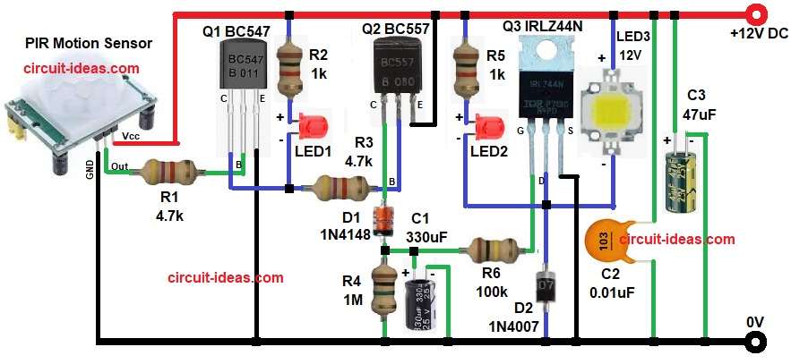
At first, the PIR sensor keeps watching for motion; normally, PIR output is LOW, so transistor Q1 BC547 stays OFF.
When motion comes then PIR output becomes HIGH, then current goes to base of Q1 through resistor R1 and so Q1 turns ON; and LED1 glows and shows motion detected.
After that Q1 gives signal to Q2 BC557 through resistor R3 and then Q2 turns ON and capacitor C1 starts charging slowly.
Next, voltage reaches MOSFET Q3 gate through resistor R6, so the MOSFET turns ON and now the LED load turns ON; and LED3 shows load ON condition.
Meanwhile the capacitor C1 stores charge and even when motion stops, C1 discharges slowly through resistor R4, because of this the MOSFET stays ON for some time and this gives delay before light OFF.
Finally, when capacitor voltage becomes low the MOSFET turns OFF and hence the light turns OFF automatically.
Formula with Calculation:
- Base resistor calculation for Q1:
R1 = (Vout of PIR – 0.7) / Ib
Assuming PIR output = 3V
Base current Ib = 0.5mA
R1 = (3 – 0.7) / 0.0005
R1 = 4600 ohm
So , nearest standard value used in our circuit is 4.7k
2. Timing delay calculation using R4 and C1:
Delay time T = R4 x C1
- R4 is 1M ohm
- C1 is 330uF
T = 1,000,000 x 330 x 10^-6
T = 330 seconds approximately
How to Build:
To build a Automatic PIR Motion Sensor Light Circuit follow the below steps:
- First, gather all the parts as shown in circuit diagram.
- Next, PIR Sensor Vcc pin connect to +12V, GND pin connect to ground and OUT pin connect to base of Q1 through resistor R1.
- Then BC547 transistor Q1 base pin connect to R1, emitter pin connect to ground and collector pin goes to LED1 and R1.
- After that, BC557 transistor Q2 emitter pin goes to +12V, base connects between collector of Q1 and LED1 through resistor R3 and collector connects to diode D1.
- Now IRLZ44N MOSFET Q3 gate pin goes from R6, drain pin connects to load and LED3 and source pin connect to ground.
- Also, capacitors C1 positive connects to diode D1 output and C1 negative goes to ground.
- Further, C2 and C3 connected across supply for noise filtering.
- Finally, diode D1 1N4148 connected for timing isolation and diode D2 1N4007 connected across load for protection.
Conclusion:
To conclude, this Automatic PIR Motion Sensor Light Circuit is simple and reliable and it is good for home, corridor and outdoor places.
The circuit saves electricity and gives more convenience and safety and also with small changes it can control high power lights too; so, this project is very good for beginners and practical use.