Want to build a smart sound circuit controlled by light? then this simple yet interesting electronics project is a perfect choice, which uses an LDR and 555 timer IC to generate different tone or beep sounds whenever the light level changes, making it best for alarms, warning systems and beginner electronics projects.
The 555 timer works in astable multivibrator mode, so it keeps generating continuous pulse signals and these pulses create frequency sound through the speaker, also the LDR changes the pulse frequency according to the light level.
So, this Automatic Tone Generator using LDR and 555 IC is a perfect project that produces different tone sounds based on light intensity.
Circuit Working:
Parts List:
| Components | Values | Quantity |
|---|---|---|
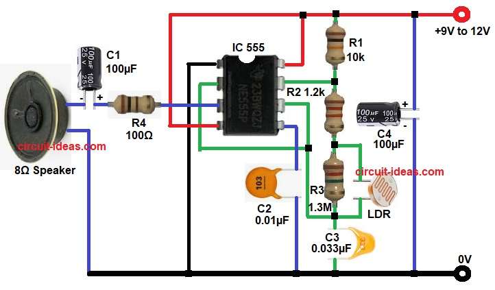
| Resistors | 10k, 1.2k, 1.2M, 100Ω | 1 each |
| LDR Light Dependent Resistor | 1 | |
| Capacitors | Ceramic 0.033µF, 0.01µF | 1 each |
| Electrolytic 100µF 25V | 2 | |
| Semiconductors | 555 Timer IC | 1 |
| 8Ω Speaker | 1 | |
| Power Supply 9V to 12V DC | 1 |
First, the LDR senses the surrounding light and when the light intensity increases the resistance of the LDR decreases and on the other hand, when the light becomes low the resistance increases.
Next, this resistance change affects the voltage at pin 2 and pin 6 of the 555 timer IC, because of this the IC starts working in astable mode and produces a square wave output at pin 3.
Then, the output signal passes through resistor R4 and capacitor C1 to the 8 ohm speaker and as a result, the speaker produces a tone sound.
Moreover, resistors R1, R2 and R3 help in setting the charging and discharging path of capacitor C3, due to this the frequency of the sound depends on the resistor values and capacitor value.
Also, capacitor C4 filters the supply voltage and gives stable operation, similarly capacitor C2 reduces noise at pin 5 or control pin area and improves performance.
How to Build:
To build a Automatic Tone Generator Circuit using LDR and 555 IC follow the below connection steps:
- First, collect all the components according to the circuit diagram.
- Now start with pin 1 of IC and connect directly to ground.
- Pin 2 connect to one terminal of capacitor C3 and also connect pin 2 with pin 6.
- Pin 3 connect to resistor R4 and capacitor C1 and speaker output.
- Pin 4 connect directly to positive supply of +9V to +12V.
- Pin 5 connect to capacitor C2 and ground.
- Pin 6 connect with pin 2 and also connect it to the capacitor C3 junction and LDR network.
- Pin 7 connect between the resistor chain R1, R2 and R3 as shown in the diagram.
- Pin 8 connect directly to the positive supply.
- LDR connect between the resistor junction and pin 2/pin 6 line exactly as shown in diagram and this part controls the tone with light.
- Power supply finally, connect to +9V to +12V DC supply and then connect capacitor C4 across supply for filtering and ground.
Conclusion:
To conclude, this Automatic Tone Generator Circuit using LDR and 555 IC is very simple and easy to build.
Moreover, it gives a sound output based on the light falling on the LDR.
Therefore, beginners can use this project for learning sensor circuits and 555 timer working and also, this circuit is useful for light alarm, automatic sound systems and educational electronics projects.
Leave a Reply