DC-DC Inverting Converter Circuit for 15V Output is of special type of circuit which changes positive voltage to negative voltage.
This circuit is useful for things which need negative power like op-amps, analog and communication devices.
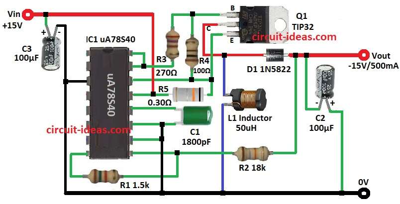
The circuit uses uA78S40 IC and a switching regulator.
It takes +15V DC in and give -15V out and handle 500mA current
It can give peak 1.5A current too!
Circuit work good and is quite cheap and is also best for low to medium power use.
Circuit Working:
Parts List:
| Component Type | Value | Quantity |
|---|---|---|
| Resistors (All resistors are 1/4 watt unless specified) | 1.5k | 1 |
| 18k | 1 | |
| 270Ω | 1 | |
| 100Ω | 1 | |
| 0.30Ω | 1 | |
| Capacitors | PPC 1800pF | 1 |
| Electrolytic 100µF 25V | 2 | |
| Semiconductors | IC uA78S40 | 1 |
| PNP Transistor TIP32 | 1 | |
| Schottky Diode 1N5822 | 1 | |
| Inductor 50µH | 1 |
uA78S40 IC is special regulator which uses external transistor Q1 as switch.
Switch control energy in inductor L1.
Power from +15V Vin input.
Inside uA78S40 small oscillator make switching pulse for Q1.
Q1 ON then current flow in L1 and store energy in magnetic field.
Q1 OFF then L1 release energy and diode D1 make negative -15V output.
Capacitor C2 smooth output and reduces ripples.
Resistor R5 check current and keep it steady.
R1 and R2 set output voltage with IC feedback.
Capacitor C1 control switching speed.
Formulas with Calculations:
Output voltage Vout calculate by:
Vout = -((R2 / R1) + 1) * Vref
where,
- Vref for uA78S40 is 1.25V
- R1 is 1.5k
- R2 is 18k
Put values:
Vout = -((18k / 1.5k) +1) * 1.25 = -15V
Inductor L calculate by:
L = (Vin * (Vout – VD)) / (Iout * f * k)
where,
- Vin is 15V
- Vout is -15V
- VD is 0.4V which is diode drop
- Iout is 0.5A
- f is 100kHz
- k is 0.5
Put values:
L = (15 * (15 – 0.4)) / (0.5 * 100000 * 0.5) = 50µH
Current sense resistor Rsc:
Rsc = 0.6V / Ilimit
where,
- Ilimit is 2A
- Rsc is 0.6 / 2 = 0.3Ω
How to Build:
To build a DC-DC Inverting Converter Circuit for 15V Output following steps are required to follow for connections:
- Put all parts like above circuit show.
- Connect pin 3 of IC1 uA78S40 to GND.
- Connect pin 8 to pin 9 of IC1 through resistor R1.
- Connect pin 10 to pin 11 and GND.
- Connect pin 12 to one side of capacitor C1 and other side of C1 connect to GND.
- Put resistor R5 between pin 13 and pin 14.
- Connect pin 15 to pin 16.
- Connect base of transistor Q1 to one side of resistor R3 and other side of R3 goes to pin 15 and 16.
- Connect one side of resistor R4 from pin 14 to base of Q1.
- Connect one side of inductor L1 to collector of Q1 and other side connect to GND.
- Connect cathode of diode D1 to collector of Q1 and anode of D1 goes to -15V output negative.
- Connect one side of resistor R2 from pins 8 and 9 to between diode D1 and -15V output.
- Connect negative side of capacitor C2 to -15V output and positive side to GND.
- Connect +15V input positive to pin 13 of IC1.
- Connect positive of capacitor C3 to +15V input and negative of C3 connect to GND.
Conclusion:
This DC-DC Inverting Converter Circuit for 15V Output uses IC uA78S40.
It changes +15V input to -15V output.
This is an simple and good circuit which give steady negative voltage for many electronics.
External transistor help handle more power.
Current sense resistor and protect from overload.
If required change resistor values to get different output voltages.
Leave a Reply