Normal battery DC cannot power it.
EL wire is thin, bright and flexible and it is used in art, clothes, signs and lights.
It needs high voltage AC from 100 to 200V with 1 to 5 kHz.
So, need EL wire inverter circuit where it changes low voltage DC to high voltage AC.
It uses 555 timer to make high frequency signal and transformer makes it stronger.
Designing an EL Wire Power Supply Circuit is cheap, small and easy.
It is good for beginner and hobby person.
This circuit is with simple parts and easy to build.
We should remember to power EL wire well.
Circuit Working:
Parts List:
| Component Type | Descriptions | Quantity |
|---|---|---|
| Resistors | 1.2k, 3.3k, 560Ω 1/4 watt | 1 each |
| Capacitors | Ceramic 0.01μF, 0.1μF | 1 each |
| Semiconductors | IC 555 | 1 |
| NPN Transistor BC547 | 1 | |
| Transformer Audio Transformer | 1 | |
| 9V DC Battery | 1 |
9V battery gives power.
555 IC1 work in astable mode and make square wave nonstop.
R1, R2 and C2 control wave frequency.
Square wave goes to Q1 transistor base through R3.
R1, R2, R3 set wave speed and stable work.
C1 and C2 help smooth wave and remove noise.
Q1 make signal strong which is enough power for transformer.
Transformer get strong signal in primary coil.
It changes low DC to high AC for EL wire.
EL wire connect to transformers high AC output.
High AC excite phosphor in EL wire and it glow.
Formulas and Calculations:
1: Frequency of Oscillation:
R1, R2 and C2 set the 555 IC wave speed (frequency) in astable mode.
Formula:
f = 1.44 / ((R1 + 2 × R2) × C2)
Values:
R1 = 1.2k = 1200Ω
R2 = 3.3k = 3300Ω
C2 = 0.1μF = 10⁻⁷ F
Values:
f = 1.44 / ((1200 + 2 × 3300) × 0.1 × 10⁻⁶)
f = 1.44 / (7800 × 0.1 × 10⁻⁶)
f = 1.44 / 7.8 × 10⁻⁴
f = 1846 Hz = 1.86 kHz
2: Duty Cycle
Duty cycle (%) = ((R1 + R2) / (R1 + 2 × R2)) × 100
Values:
= ((1200 + 3300) / (1200 + 6600)) × 100
= (4500 / 7800) × 100
= 57.69%
So wave runs at 1.86 kHz with 57.69% duty.
How To Build:
For Designing an EL Wire Power Supply Circuit following are the below mentioned steps to follow:
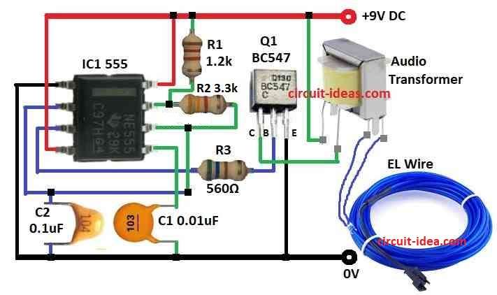
- Take all parts shown in circuit diagram.
- Connect pin 1 of 555 IC1 to GND.
- Connect pin 2 to pin 6 and also connect to GND using capacitor C2.
- Connect pin 3 to base of transistor Q1 using resistor R3.
- Connect pin 4 and pin 8 to +9V DC.
- Connect pin 5 to GND using capacitor C1.
- Connect pin 6 to pin 7 through resistor R2.
- Connect pin 7 to +9V DC through resistor R1.
- Connect collector of Q1 to one wire of audio transformer of primary side.
- Connect other primary wire of transformer to +9V DC.
- Connect emitter of Q1 to GND.
- Connect secondary wires of transformer to EL wire.
Conclusion:
This Designing an EL Wire Power Supply Circuit is useful to light up EL wires.
It uses 555 timer and simple transformer to change low DC to high-frequency AC.
This circuit is good for students and hobby people to learn basic electronics and how AC is made from DC.