Modern devices and homes need good temperature control.
It help gadgets live long and make place comfortable.
One example is fan with temperature control.
Fan change speed by room temperature.
This keep temperature okay, save power and with less noise.
IC LM35 sensor is used for check the temperature.
When it is too hot 5V relay turn ON the fan to cool the room.
This project for DIY Temperature-Controlled Fan Circuit with Arduino is a useful project.
Arduino is easy and popular for smart temperature system.
It makes sensor and device connection simple.
Coding:
#include <SoftwareSerial.h>

const int tempPin = A0; // Analog pin for temperature sensor
const int relayPin = 2; // Digital pin for relay
const int thresholdTemp = 30; // Temperature threshold in degrees Celsius

void setup() {
  Serial.begin(9600);
  pinMode(relayPin, OUTPUT);
}

void loop() {
  int sensorValue = analogRead(tempPin);
  float temperature = (sensorValue / 1023.0) * 5.0 * 100.0; // Convert sensor value to temperature

  Serial.print("Temperature: ");
  Serial.print(temperature);
  Serial.println(" degrees Celsius");

  if (temperature >= thresholdTemp) {
    digitalWrite(relayPin, HIGH); // Activate relay
    Serial.println("Fan turned on");
  } else {
    digitalWrite(relayPin, LOW); // Deactivate relay
    Serial.println("Fan turned off");
  }

  delay(1000); // Delay for 1 second
}
Code Explanation:
- #include SoftwareSerial library was added but not needed so removed.
- const int tempPin = A0;
- Sensor connected to analog pin A0.
- const int relayPin = 2;
- Relay connected to digital pin 2.
- const int thresholdTemp = 30;
- Fan will turn on if temperature goes over 30°C.
- Serial.begin(9600);
- Start serial monitor to send/receive data.
- pinMode(relayPin, OUTPUT);
- Set relayPin as output to control relay.
- int sensorValue = analogRead(tempPin);
- Read sensor value from tempPin.
- float temperature = (sensorValue / 1023.0) * 5.0 * 100.0;
- Convert sensor value to Celsius.
- LM35 gives 0 to 5V which is equal to 0 to 100°C.
- Serial.print(“Temperature: “);
- Print “Temperature:” to serial monitor.
- Serial.print(temperature);
- Print real temperature value.
- if (temperature >= thresholdTemp) {
- Check if temperature is 30°C or more.
- digitalWrite(relayPin, HIGH);
- Turn ON relay (fan ON).
- Serial.println(“Fan turned on”);
- Show message fan is ON.
- } else {
- If temperature is less than 30°C,
- digitalWrite(relayPin, LOW);
- Turn OFF the relay (fan OFF).
- Serial.println(“Fan turned off”);
- Show message fan is OFF.
- delay(1000);
- Wait 1 second before checking again.
Circuit Working:
Parts List:
| Component | Quantity |
|---|---|
| Arduino UNO board | 1 |
| IC 7809 voltage regulator | 1 |
| IC LM35 temperature sensor | 1 |
| 5V single channel relay | 1 |
| 220V AC fan | 1 |
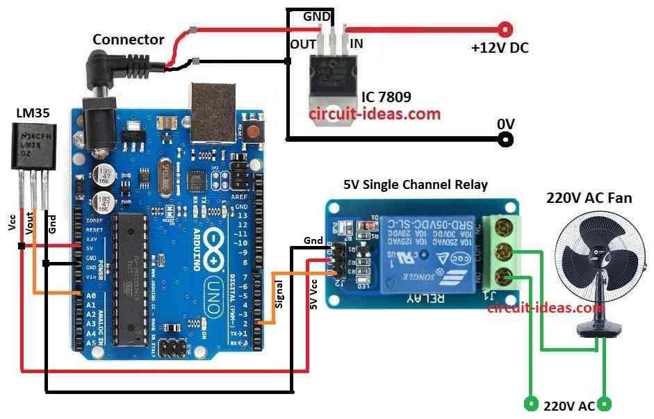
This above circuit for temperature control fan is simple to make, IC LM35 sensor has 3 pins: VCC, GND and analog out.
Where VCC connect to Arduino 5V, GND connects to Arduino GND and Analog pin connect to A0 of Arduino.
IC 7809 is used to drop 5V to 3.3V for LM35 power.
LM35 gives voltage based on temperature and Arduino reads this voltage on analog pin.
Arduino compare temperature with set value.
5V relay is used to turn ON/OFF the fan and this relay can control high power devices with low signal.
If temperature goes above 30°C then relay turns ON and then this relay connects 220V AC fan to power.
Fan starts cooling when relay turns ON.
Arduino turns ON relay when LM35 shows temperature above 30°C and this helps to keep temperature in limit.
If temperature is below 30°C then Arduino keep relay OFF and fan also stays OFF.
Fan works only when needed and this saves power and keeps room cool.
How to Build:
To build a DIY Temperature-Controlled Fan with Arduino following are the steps to follow:
- Gather all parts from the circuit diagram.
- Use IC1 7809 to give stable 9V DC to Arduino.
- Connect LM35 VCC pin to Arduino 5V pin.
- Connect LM35 Vout pin to A0 on Arduino.
- Connect LM35 GND pin to Arduino GND pin.
- Connect Relay signal pin to pin 2 on Arduino.
- Connect Relay COM pin to Arduino 5V pin.
- Connect Relay GND pin to Arduino GND.
- Connect one wire of AC fan to 220V AC and other wire to Relay COM pin.
- Connect Relay NO pin to 220V AC.
Conclusion:
This project for DIY Temperature-Controlled Fan Circuit with Arduino shows Arduino can do everyday life auto control.
The fan turns ON/OFF by room temperature.
System helps keep place cool.
More features like logging or fan speed control can be added by changing code
Leave a Reply