L293D is small chip which control speed and direction of DC and stepper motors.
People use it a lot in robots and automation.
It uses H-bridge system to change motor direction by flipping voltage.
Chip can run 2 motors at same time.
Each motor get up to 600 mA current which is good for small and big projects.
L293D have built-in diodes and these protect chip from back power when motor stops and make chip last long.
This circuit for Exploring the L293D H-Bridge Motor Driver Circuit works easy with Arduino, Raspberry Pi and is good for hobby and professional people.
With PWM, L293D help control motor speed and make movement smooth and correct.
Circuit Working:
Parts List:
| Component | Quantity |
|---|---|
| DC Motors | 2 |
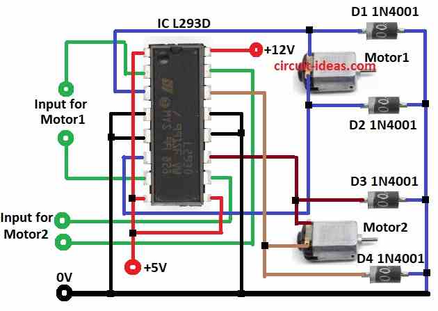
| IC L293D | 1 |
| Diodes 1N4001 | 4 |
H-Bridge motor driver give power and signals to motor and make it run how we want.
L293D is strong chip and it can control 2 motors at same time.
It works with 4.5V to 36V and give current up to 600 mA both ways.
Chip has 16 pins which is good for noise protection and safety from static (ESD).
Circuit is simple and needs only 4 extra diodes for more safety.
Each motor uses 2 input pins and 2 output pins like:
Motor 1: input at pin 2 and 7 and output at pin 3 and 6.
Motor 2: input at pin 10 and 15 and output at pin 11 and 14.
Diodes D1 to D4 stop damage from reverse voltage when motor turns OFF.
Formulas:
L293D H-Bridge Motor Driver with Important Formulas:
Motor Speed Control:
Use PWM (Pulse Width Modulation) to control motor speed.
Formula:
Vavg = Vsupply × D / 100
where,
- D is the duty cycle in %
- Vavg is the average voltage to motor
Power Used by Motor:
Formula:
P = Vmotor × Imotor
where,
- Vmotor is the voltage on motor
- Imotor is the current in motor
Current Rating:
L293D max is 600 mA per channel and it does not goes over this.
Total power from supply:
Ptotal = Vsupply × Itotal
where,
- Itotal is the current of both motors together
Heat/Temperature Check:
To find power loss (heat) in chip:
Pdissipation = (Vsupply − Vmotor) × Imotor
This helps check if chip is getting hot.
Note:
Check all wires are correct.
If using more current then use heatsink for safety.
With these formulas L293D can control 2 motors well.
How to Build:
For Exploring the L293D H-Bridge Motor Driver Circuit follow the below mentioned construction steps for connections:
Collect all parts shown in circuit diagram.
Motor1 Wiring:
- First pin of Motor1 connects to pin 3 of L293D
- Second pin of Motor1 connects to pin 6 of L293D
Motor2 Wiring:
- First pin of Motor2 goes to pin 11 of L293D
- Second pin of Motor2 goes to pin 14 of L293D
Diode Protection:
- Diode D1 to D4 cathodes connect to motor terminals
- All diode anodes connect to GND
Motor1 Input Pins:
- First input connects to pin 2 of L293D
- Second input connects to pin 7 of L293D
Motor2 Input Pins:
- First input connects to pin 10 of L293D
- Second input connects to pin 15 of L293D
GND Connections:
- Pins 4, 5, 12, 13 connects to GND
- Pins 1, 8, 9 goes to +5V
- Pin 16 goes to +12V
Conclusion:
Exploring the L293D H-Bridge Motor Driver Circuit is easy and useful to control two DC motors.
It has built-in safety, simple wiring and can drive motors in both directions.
With few parts it gives strong and safe motor control for robots and automation projects.
References:
A general question regarding a simple DC Motor combined with an H-Bridge (L293D)