This small and simple Fatigue Testing Circuit is a fun way to check whether someone feels tired or not! it makes LED blink very fast and we can change how fast it blink.
Also, if we are not tired, we can still see the LED blink even when it flashes fast; however, if we are tired, the LED blink may look slow or we may not see it at all.
Hence, this happens because our brain cannot keep up with very fast blinking and if someone can still see the fast blink, then they may not feel very tired.
Circuit Working:
Parts List:
| Components | Quantity |
|---|---|
| Resistors | |
| 47k 1/4 watt | 1 |
| 100k 1/4 watt | 1 |
| 390Ω 1/4 watt | 1 |
| Potentiometer 250k | 1 |
| Capacitors | |
| Ceramic 0.1µF | 1 |
| Semiconductors | |
| IC 555 | 1 |
| LED 5mm 20mA | 1 |
| Battery 9V | 1 |
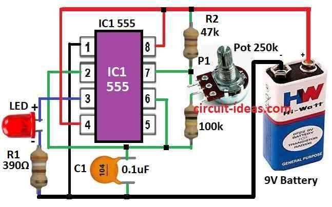
To begin with, this tired checking circuit uses 555 IC working like astable multivibrator, as it checks how tired person is by seeing how good they see blinking light.
Also, this circuit is easy to make as one LED blinks from 555 IC output and we can change blink speed using P1 potentiometer.
Here, the blink can go from 20 to 50 times in one second and people see blink best when it flash around 30 to 40 times per second.
Formula:
This formula show how to find frequency for 555 IC working in astable mode with circuit above:
F = 1.44 / (R1 + 2R2) × C
where,
- F is frequency in hertz Hz
- R1 is resistor R1 value in ohms Ω
- R2 is resistor R2 value in ohms Ω
- C is capacitor value in farads F
This formula think duty cycle is almost 50%, that mean how long output stay ON compare to full cycle time.
How to Build:
To build a Simple Fatigue Testing Circuit one need to follow the below mentioned steps:
Connect the 555 IC:
- First, put 555 IC on breadboard and pin 1 connects to ground and pin 8 to power VCC.
Make astable setup:
- After that, connect pin 4 to VCC which turn off reset.
- Connect pin 2 and pin 6 together and then connect pin 6 to pin 7 with 10k resistor.
- Also, pin 7 connects to ground using a potentiometer.
- Connect pin 6 and pin 2 with 0.1µF capacitor.
Connect the LED:
- Long leg anode of LED connects to pin 3 of 555 using 390Ω resistor and short leg cathode connects to ground.
Add potentiometer:
- One side of 100k potentiometer P1 connects to VCC and other side to ground and also middle pin wiper will connect to pin 7 of 555 IC.
Give power to circuit:
- Connect power supply and then connect positive to pin 8 of VCC and connect Negative to ground.
Change the blink speed:
- Turn potentiometer P1 to change blink speed of LED and then LED can blink between 20 to 50 times per second Hz.
Optional: Add switch and box:
- One can add switch to turn ON/OFF easily and we can put everything in box to keep safe and clean.
Test circuit:
- Turn ON the power and observe the LED, if the LED blinks fast and we can still see the blinking, then we may not feel tired.
- However, if the LED blinks fast and we cannot see the blinking clearly, then we may feel tired.
Note:
- Be careful while working with electronics and if one is not sure about electronics ask someone who knows better.
Conclusion:
To conclude, this Simple Fatigue Testing Circuit use blinking light from oscillator usually 555 IC, as it make LED blink at different speeds.
Moreover, by checking when person stop seeing the blink we can guess how tired they are and if they do not see fast blink maybe they are more tired.
As a result, this way circuit gives simple and useful way to test tiredness using eyes and fast light.

Leave a Reply