For fun and learning project, we will learn about basic electronics, coding and sensor uses.
Here, we will learn How to Create a Water Level Sensor Circuit with Arduino and this guide teaches us how to make water sensor.
Furthermore, it is good for stopping overflow, checking water in tank or auto watering plants.
We can use Arduino Uno which is easy and flexible, water sensor, IC 7809, LED and resistor, so follow steps to connect parts, write code, send to Arduino and read water level data to do actions.
Arduino Code:
const int waterSensorPin = 2; // Replace 2 with the actual pin number used for the water level sensor

void setup() {
  pinMode(waterSensorPin, INPUT);
  Serial.begin(9600);
}

void loop() {
  int sensorValue = digitalRead(waterSensorPin);

  if (sensorValue == HIGH) {
    Serial.println("Water detected");
  } else {
    Serial.println("No water detected");
  }

  delay(1000); // Delay for 1 second
}
Code Explanation:
- WaterSensorPin is the pin number for water sensor.
- In setup() WaterSensorPin set as input and serial starts at 9600 speed.
- In loop(), digitalRead() check value from WaterSensorPin.
- If value is HIGH that means water is there and will show message in serial monitor.
- If the signal reads LOW, the sensor detects no water
- The program uses a one-second delay so the serial monitor does not display too many messages.
Circuit Working:
Parts List:
| Components | Quantity |
|---|---|
| Resistors | |
| 220Ω 1/4 watt | 1 |
| Semiconductors | |
| Arduino UNO board | 1 |
| IC 7809 | 1 |
| Water level sensor | 1 |
| Red LED 5mm 20mA | 1 |
| Multimeter | 1 |
| Probes Red and Black | 2 |
In this circuit when water drop falls in glass the output pin voltage goes up with water level and this happens because sensor part on PCB feels water and changes voltage.
Water level sensor has two probes, one probe goes in water and lets current flow and other stays dry as reference.
IC 7809 gives steady 9V power to Arduino and sensor and sensor module has 3 pins and 2 are power pins.
Then connect them to Arduinos 5V and GND and this makes circuit work well.
After that, the LED and resistor indicate whether water is present.
If the sensor detects water, the LED turns ON and the resistor limits the current to prevent the LED from burning out.
How to Build:
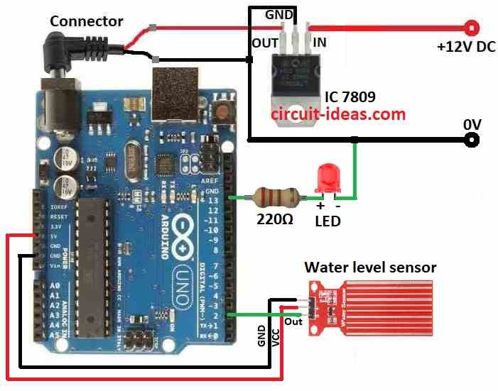
To build a Water Level Sensor Circuit with Arduino follow below steps for connections:
- First, collect all parts as shown in the circuit diagram.
- Next, connect IC 7809 to give steady 9V power to Arduino.
- Now GND pin go to Arduino GND, VCC pin go to Arduino 5V and then OUT pin go to Arduino pin 2
- Then Arduino pin 13 connects to 220Ω resistor and with red LED in series with short leg cathode of LED connects to Arduino GND
Testing:
- Take a multimeter to check voltage or resistance.
- Then use a container with water like a tap or small tank.
- Power Arduino by plugging into PC and then set multimeter to DC voltage mode.
- Connect Multimeter positive probe to sensor OUT pin and multimeter negative probe connects to sensor GND pin
- When sensor is dry check multimeter reading.
- Voltage may be HIGH or LOW it depends on sensor type and then slowly put sensor in water.
- Voltage should change with LOW to HIGH or vice versa and be sure voltage change matches the Arduino code.
- For example: HIGH means water found and LOW means no water.
- Finally, repeat steps 10 to 12 a few times to get steady correct results.
Conclusion:
To conclude, using parts from circuit diagram and steps above we can make working circuit that checks if water is there or not.
We can also add more smart features later like turning on alarm or controlling other devices based on water level.
Leave a Reply