In motor work people try new ideas with permanent magnets.
In 1979 Donald Kelly made this new type of motor with magnets, design was special, easy to build and uses magnets in smart way.
Also, this article talk about Exploring Free Energy Concepts in Permanent Magnet Motors.
Below lets explore the concept of permanent magnet motor with free energy:
In 1979 Donald Kelly made engine with magnets and he says motor turn slow and magnets are hard to move.
To fix he used small motors to help move magnets and this made motor easy to understand; also his way is same like Stephen Kundel who use coils to move magnets.
Kelly wants to use small electricity and get more power from magnets so motor spins faster and stronger.
Kellys Magnet Motor Design:
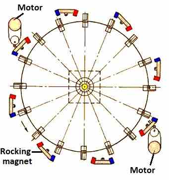
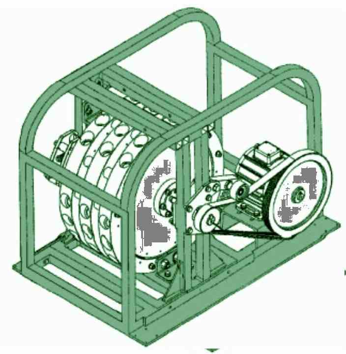
Kellys Magnet Motor:
Kelly motor have eight moving magnet groups.
First they pull spinning part and when slow down the magnets move to new place and then they stop pull and start push.
Motor spin from push and pull and then magnets give power so helper motors use little electricity.
So w can use coils instead of helper motors and if motor make enough power then maybe it can run itself; also add more magnet layers to make stronger.
Mike Bradys “Perendev” Magnet Motor:
Mike Brady made a magnet motor called “Perendev”
It sparked the curiosity of many people and some claim that manufacturers built and sold many of these motors, each producing at least 100 kW of power.
Problems with Bradys Perendev Motor:
Only Sterling Allan did small test but no one else said anything about it works.
Making motor run only with magnets is very hard.
So better to start with motors that move magnets or use special cover like Adams or Charles Flynn motor.
Bradys Motor Issues:
Bradys motor uses rare and costly magnets which are hard to find, he also needs special cover to protect magnets.
By 2010 he can’t sell motor good, this made investors unhappy.
If Brady can’t build motor again then beginners should try simple motors like from Don Kelly, Stephen Kundel, Charles Flynn, Robert Tracy or Jines.
These motors use moving magnets or covers.
Blocking Magnetic Fields:
Pasi Makila from Finland found a way to block magnetic force using normal materials, he covered a round magnet with layers of aluminum and flat steel.
This blocked most of the magnetic field.
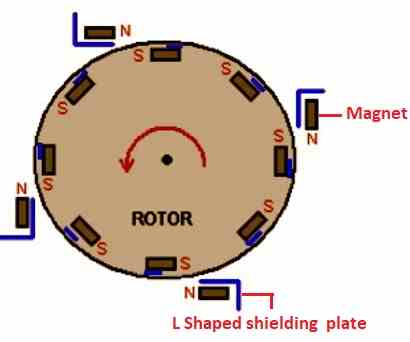
Makilas Magnetic Cover Idea:
Makila says use 4 steel layers with aluminum between and maybe more aluminum outside and this cover can stop motor magnets from spin backward.
In this motor the standing magnet north pulled by spinning magnet south.
When south pass north then cover stop magnet from pulling back.
A side cover on the spinning magnet also prevents the magnets from pushing against each other, but the idea remains unbuilt.
Two Motors That Spin:
Fridge magnets stick because the steel in refrigerators reacts to magnetic fields.
Important Note About Steel and Iron:
This is important when we use steel or iron to block magnets as steel and iron can become magnet too.
If steel fully covers a magnet, the magnet still pulls other magnets toward it.
Two Magnet Gears Idea:
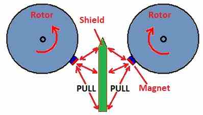
Idea use two gears with magnets on them then metal shield goes in middle of gears and then magnets spin then they touch shield.
To make it easy diagram show only one magnet pair.
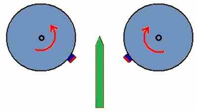
How the Metal Shield Works:
Metal shield pull each magnet and make rotors turn same way as red arrows.
Normally when magnets match with shield the rotors stop, but idea is to change shield shape and make it thin at end.
Thin part help back magnet pull line up with front magnet.
At the shield tip, the push and pull forces cancel each other, so no force acts there.
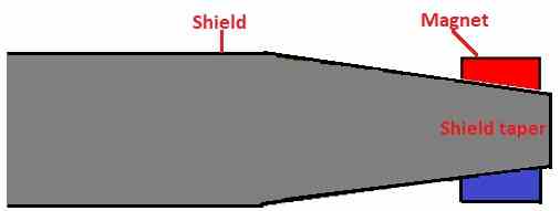
To find good shape for taper shield we need testing and it depend on magnet power, shield size, material and space between parts.
Shield tip has neutral zone with no strong pull so rotors can keep spinning after the shield.
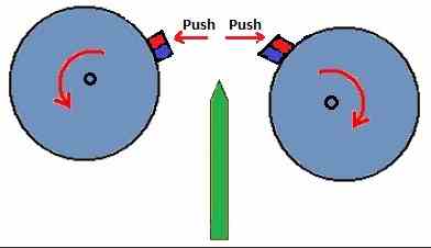
When magnets go outside the shield they push each other hard and this push make rotors turn.
One magnet pair can make spin and more magnets make it stronger.
So we can put one more magnet pair same place to see how shield pull and magnet push work together.
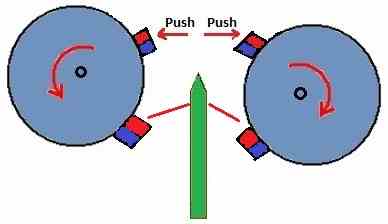
Magnet Motor with Shield Setup:
In this setup rotors may spin all time. and to stop it just take out the shield.
Magnets set in repulsion mode and same poles face each other, but repulsion can make magnets weak after some time.
This design does not use attraction mode but it is easy to remove magnets, as attraction mode is better and magnets stay strong and easy to change or fix.
Conclusion:
In this post about Exploring Free Energy Concepts in Permanent Magnet Motors many people try to make free energy using magnets.
Kelly use small motors to help magnets spin.
Bradys motor is strong but hard to test and Makila have idea to stop magnets move backward.
Some motors use magnet push to keep spinning and these ideas are not perfect but good to learn and test.
Leave a Reply