We can learn How To Test a Multi-Core Wire using Cable Tester Circuit through this tutorial.
This tool check if cable is working or not.
It find wrong connection like short or broken wire.
Circuit is good for multi-core cable with many wires inside.
It help check all wires are okay.
We can also use simple multimeter to see if wire is connected from one end to other.
Circuit Working:
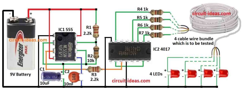
Parts List:
| Category | Item | Quantity |
|---|---|---|
| Resistors | 2.2k 1/4 watt | 2 |
| 10k 1/4 watt | 1 | |
| 1k 1/4 watt | 4 | |
| Capacitors | Ceramic 10nF | 1 |
| Electrolytic 10μF 25V | 1 | |
| Semiconductors | IC 555 | 1 |
| IC 4017 | 1 | |
| LEDs red 5mm 20mA | 4 | |
| 4 cable wire bundle | 1 | |
| 9V Battery | 1 |
This multi-wire cable tester circuit help check if any wire in cable is bad or broken.
It uses special part called IC1 555 and this part makes steady electric pulse like a clock tick.
Three small parts in circuit can change how fast the pulses go.
We can use online calculator to choose right parts for good LED blink speed.
Another part is IC2 4017 which is special counter chip.
And it gets pulses from IC1 555.
This chip count up to four and it has four outputs.
Each output goes to one LED.
As it count it turn ON one LED at a time in order.
We connect its fifth output which is not for LED to reset pin.
So after fourth LED lights the fifth pin resets the counter and then the first LED lights again.
This make a loop and LEDs keep blinking one by on, again and again.
If wire is good then the LED will blink when its the turn.
If wire is broken then the LED will not blink with no power reaches it.
So if all four LEDs blink in order then cable is good.
If any LED does not blinks then that wire is broken.
Formula:
This circuit uses 555 IC to make clock signal like ON-OFF pulses.
How fast it blinks depends on two resistors R1 and R2 and one capacitor C1.
The formula to find blink speed means frequency is:
Frequency (f) = 1 / (0.693 × (R1 + 2 × R2) × C1)
where:
- f is how fast the blink is in hertz Hz
- R1 is the value of resistor 1 in ohms Ω
- R2 is the value of resistor 2 in ohms Ω
- C1 is the value of capacitor 1 in farads F
This formula helps us know how fast LEDs will blink in cable tester.
How to Build:
To build a Multi-Core Wire using Cable Tester Circuit following are the steps for connections:
- Gather all parts as shown in the circuit diagram.
- Connect pin 1 of IC1 555 to ground.
- Connect pin 2 to pin 6 of IC1 through capacitor C1.
- Connect pin 3 of IC1 to pin 14 of IC2 4017 using resistor R3.
- Connect pin 4 and pin 8 of IC1 to +9V battery.
- Connect pin 5 of IC1 to ground using capacitor C2.
- Put resistor R2 between pin 6 and pin 7 of IC1.
- Put resistor R1 from pin 7 to +9V supply.
- Connect pin 2, 3, 4 and 7 of IC2 4017 to one side of 4 cable wires using resistors R4, R5, R6, R7.
- Connect other side of those 4 cable wires to 4 red LEDs.
- Connect pin 8 and pin 13 of IC2 to ground.
- Connect pin 10 to pin 15 of IC2 for reset loop.
Safety Tips:
- Always use the tester with low voltage under 24V to stay safe.
- If anyone is new to electronics then it is better to use ready made cable tester.
- Be careful with safety first, with wrong handling can cause damage or shock.
Conclusion:
This How To Test a Multi-Core Wire using Cable Tester Circuit helps test 4 wire cables.
Blinking LEDs show if wires are good or broken.
Make it ourselves, test cables fast and fix them easily.