This circuit turns a normal stick into a smart safety tool for blind users, as it helps blind person know if any object is near.
Also, it uses an IR sensor, a transistor, a buzzer and a 5V regulator IC, here, the IR sensor detects objects that human eyes cannot see. Furthermore, this IR Sensor Based Stick for Blind Circuit costs very little and provides great help to visually impaired people.
Therefore, this is a small circuit but with big purpose and its parts are cheap and easy to find.
Circuit Working:
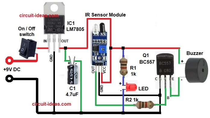
Parts List:
| Components | Quantity |
|---|---|
| Resistors | |
| 1k 1/4 watt | 2 |
| Capacitor | |
| Electrolytic 4.7uF 25V | 1 |
| Semiconductors | |
| IC LM7805 Voltage Regulator | 1 |
| Transistor BC557 | 1 |
| IR Sensor Module | 1 |
| Power LED any | 1 |
| Buzzer (Piezo) | 1 |
| SPST On / Off Switch | 1 |
| 9V Power Supply or 9V Battery | 1 |
To begin with, in this circuit 9V battery gives power and the switch turns the circuit ON and OFF.
The IC LM7805 regulator changes 9V to 5V and then IR sensor sends IR light out; also if object comes close then IR light reflects back.
Then sensor output becomes low or high based on module type and then this signal goes to transistor Q1 BC557.
Now, transistor turns ON when base gets signal and when transistor turns ON, buzzer makes sound.
Finally, LED also glows to show power is working and so blind person knows obstacle is near.
Formulas:
IC LM7805 gives 5V regulated output.
Dropout voltage approx 2V, so input must be above 7V.
Battery 9V used here is enough.
Base current of transistor:
Ib = (Sensor output voltage – Vbe) / R2
Assume sensor output 5V.
Vbe approx 0.7V.
R2 = 1k.
Ib = (5 – 0.7) / 1000
Ib = 4.3 mA approx.
Collector current:
Ic = hFE × Ib
Assume hFE of BC557 approx 125.
Ic = 125 × 0.0043
Ic approx 0.54 A.
Enough to drive small buzzer easily.
How to Build:
To build a IR Sensor Based Stick for Blind Circuit follow the below steps for connection:
- First, take all the parts as shown in circuit diagram.
- Next, connect 9V battery positive to switch and switch output goes to pin 1 of LM7805.
- Then connect pin 2 of LM7805 to ground.
- After that, connect pin 3 of LM7805 to positive of capacitor C1 and negative of capacitor C1 connect to GND.
- Now connect IR sensor module pin 1 VCC to 5V.
- Further, pin 2 GND go to ground and then pin 3 OUT go to transistor Q1 base through R2 resistor.
- Also, connect LED anode from resistor R1 in series and cathode of LED to GND.
- Next, connect transistor Q1 BC557 pin 1 collector go to GND, pin 2 base go to sensor output through resistor R2 and then pin 3 emitter go to buzzer negative.
- Finally, connect buzzer positive to Out pin of IC1.
Conclusion:
To conclude, this is simple IR Sensor Based Stick for Blind Circuit, as it uses IR sensor to find obstacles.
Here, the transistor and buzzer produce a sound when an object comes close, also this low cost circuit is easy to build for school and hobby projects.
Finally, it helps blind person move safely without obstacles.

Leave a Reply