During electronics testing we often need variable voltage as fixed power supplies are not always suitable, but our mains electricity is AC and therefore, we must convert AC to DC before using it.
Also many projects need different voltages, like sometimes 5V or sometimes 12V or more.
For this reason adjustable power supplies are very useful.
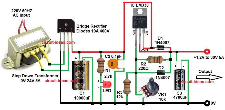
In this article IC LM338 is used, is a high current voltage regulator IC which can give adjustable output voltage, output can change from about 1.2V to 30V and it is capable of delivering up to 5A current.
This LM338 Adjustable Power Supply 5A Circuit uses transformer, rectifier and filtering capacitor and after that IC controls the voltage.
So the circuit becomes a simple adjustable DC power supply for lab and hobby use.
Circuit Working:
Parts List:
| Components | Values | Quantity |
|---|---|---|
| Resistors (All resistors are 1/4 watt) | 2.7k, 12k, 220Ω | 1 each |
| Potentiometer 10k | 1 | |
| Capacitors | Electrolytic 10000µF 50V, 4700µF 50V | 1 each |
| Ceramic 0.1µF | 1 | |
| Semiconductors | Voltage Regulator IC LM338 | 1 |
| Diodes 1N4007 | 2 | |
| Bridge Rectifier Diodes 10A 400V | 4 | |
| LED any color 5mm | 1 | |
| Step Down Transformer Primary 220V 50Hz, secondary 0V-24V 5A | 1 | |
| Large heatsink for IC LM338 | 1 |
First, 220V AC mains enters the transformer and then this transformer reduces the voltage from 220V AC to 24V AC, and this step makes the voltage safe and suitable for the circuit.
Next, the AC voltage goes to the bridge rectifier as this rectifier converts AC voltage into pulsating DC voltage.
After that capacitor C1 10000uF filters the DC voltage which removes ripple and makes the voltage smoother.
Then the DC voltage goes to the LM338 regulator IC and this LM338 controls the output voltage.
The adjustable pin of LM338 is connected with resistors and potentiometer network and when the potentiometer rotates, the output voltage changes.
Capacitor C2 improves stability of the regulator which reduces noise and oscillation.
Capacitor C3 4700uF filters the final output and therefore, the output voltage becomes smooth and stable.
Diode D1 protects the IC when input voltage suddenly drops and diode D2 protects the adjust pin.
LED with resistor works as power indicator which shows that the power supply is ON.
Finally, the output voltage becomes adjustable from about 1.2V to around 30V depending on transformer and load.
How to Build:
To build a LM338 Adjustable Power Supply 5A Circuit follow the below connection steps:
- First, collect all the circuit parts as shown in circuit diagram.
- Then start with transformer secondary to bridge rectifier AC inputs.
- Connect bridge rectifier positive output to filter capacitors positive C1 and resistor R1.
- Connect resistor R1 and LED in series from input pin of IC and GND.
- Input pin of IC connects to filtered DC from the rectifier.
- Output pin of IC connects to the output terminal of 1.2V to 30V power supply.
- Adjust pin of IC connects to the resistors network of R2, R3, VR1 and diode D2 anode.
- R2 220 ohm resistor connects between output pin and adjust pin.
- VR1 10K potentiometer connects between Adjust pin and ground.
- R3 12K resistor connects from adjust pin to ground for stability.
- Diode D1 connects between output and input of LM338.
- Diode D2 connects between adjust pin and output.
- Capacitor C2 connects between input pin and GND.
- Capacitor C3 connects between output and ground.
- Finally, attach a large heatsink to LM338 because high current generates heat.
Conclusion:
LM338 Adjustable Power Supply 5A Circuit is a simple and useful which can provide stable and variable DC voltage.
The circuit uses few components and is easy to build and also it can deliver high current up to 5A to 10A.
Therefore, it is suitable for electronics labs, hobby projects and testing circuits.
With proper heatsink and transformer the circuit works reliably and so it becomes a good adjustable bench power supply for many applications.
Leave a Reply