In this tutorial, circuit uses a PIR sensor to control an output load through transistor switching, but the main purpose of this circuit is to turn ON the output when motion is detected and when PIR sensor detects motion, it gives a trigger signal
After that, the NPN transistor and PNP transistor work together as electronic switches and because of this, the output side gets voltage and can drive another stage, relay input, buzzer or control signal line.
Also, this circuit gives signal conditioning and switching action in a simple way, as it uses one NPN transistor BC547 and one PNP transistor BC557.
Therefore, the circuit becomes with low cost and easy to build.
Circuit Working:
Parts List:
| Components | Values | Quantity |
|---|---|---|
| Resistors | 4.7k | 2 |
| 1k, 1M | 1 each | |
| Capacitor | Electrolytic 330µF 25V | 1 |
| Semiconductors | Transistor BC547 NPN | 1 |
| Transistor BC557 PNP | 1 | |
| PIR Sensor Module 12V or standard PIR | 1 | |
| Standard 5 mm LED | 1 | |
| Diode 1N4148 | 1 | |
| Power Supply +12V DC | 1 |
At first, the PIR sensor gets power from +12V and GND lines and when no motion is present then the PIR output remains LOW or inactive.
When PIR detects motion then PIR output becomes HIGH, this signal goes through resistor R1 to the base of Q1 which is BC547 NPN transistor.
As soon as base voltage becomes more than about 0.7V then Q1 turns ON and after Q1 turns ON then it pulls its collector point toward GND, then this collector point connects to resistor R3 and also LED indication path and so LED glows and shows trigger indication.
At the same time the low signal reaches base of Q2 through R3 and Q2 is BC557 PNP transistor, for a PNP transistor when base voltage becomes lower than emitter voltage by about 0.7V transistor turns ON.
Since emitter of Q2 is connected to +12V reducing base voltage turns it ON, now current flows from emitter to collector of Q2 and reaches the load output through diode D1.
Capacitor C1 charges and holds the output for a small delay time, because of this the output does not drop immediately and therefore, this circuit acts like a motion activated switch.
How to Build:
To build a PIR Sensor Based PNP Switching Circuit for Output Control follow the below connection steps:
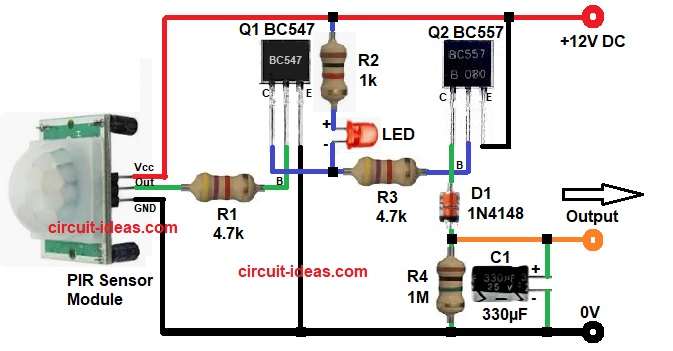
- Start, the circuit by collecting all the parts as in diagram above.
- Next, start with PIR Sensor with V+ pin connects to +12V.
- Out pin connects to R1 resistor input.
- V- pin goes to GND.
- Then start with Q1 BC547 NPN transistor base pin goes to R1 from PIR output.
- Collector pin connects to LED cathode point + R3 input.
- Emitter pin goes to GND.
- Next take Q2 BC557 PNP transistor with emitter pin connect to +12V.
- Base pin connects to R3 output.
- Collector pin goes to D1 anode side of diode.
- After that , take LED anode connects to resistor R2 side.
- Cathode goes to Q1 collector node.
- Then R2 resistor one side goes to +12V and other side goes to LED anode.
- Then resistor R3 one side connect to Q1 collector and other side connect to Q2 base.
- After that, take diode D1 with anode end goes to Q2 collector and cathode end goes to load output.
- Next, take last resistor R4 and connect one side to load output and other side goes to GND.
- Then lastly, capacitor C1 positive goes to load output and negative goes to GND.
Conclusion:
Finally, PIR Sensor Based PNP Switching Circuit for Output Control gives reliable output switching using one NPN and one PNP transistor.
First transistor amplifies the PIR signal and second transistor works as high-side switch and also, the RC network gives output hold time.
Therefore, the circuit is very useful for automation and security applications and its design is simple, easy to assemble and suitable for beginners as well as practical projects.
Leave a Reply