When we plug in Precision Electronic Rat Repellent Circuit device, it makes high loud noise that rat and mouse do not like.
Human and animal cannot hear this noise because its too high sound.
Good choice if we do not want to use poison.
It just makes strong sound wave and rat gets scared and run away.
What is Electronic Rat Repellent Circuit:
Electronic rat repellent circuit is small device which makes ultrasonic sound to keep rats and mice away.
Rat can hear very high sound like 30kHz to 50kHz which human do not can hear this.
When the rat hear this high sound then they do not feel good, so they run away from that place.
Circuit Diagram:
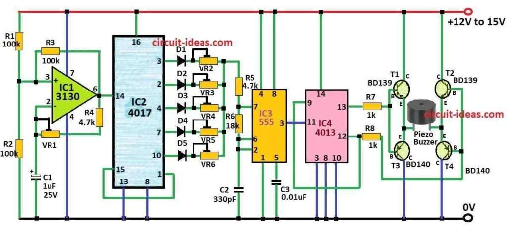
Parts List:
| Component | Quantity |
|---|---|
| Resistors (All resistors are 1/4 watt unless specified) | |
| 100k | 3 |
| 4.7k | 2 |
| 1k | 2 |
| 18k | 1 |
| Preset VR1 470k | 1 |
| Presets VR2 to VR6 100k | 5 |
| Capacitors | |
| Ceramic 330pF | 2 |
| Ceramic 0.01μF | 2 |
| Electrolytic 1μF 25V | 1 |
| Semiconductors | |
| IC 3130 | 1 |
| IC 4017 | 1 |
| IC 555 | 1 |
| IC 4013 | 1 |
| Transistors T1 and T2 BD139 | 2 |
| Transistors T3 and T4 BD140 | 2 |
| Diodes D1 to D5 1N4148 | 5 |
| Piezo Buzzer | 1 |
How to Build:
Steps to Make Precision Electronic Rat Repellent Circuit:
Make the oscillator circuit:
- Use 555 IC to make oscillator circuit.
- This circuit makes high frequency pulse.
- Add capacitor and resistor to fix sound between 30kHz and 50kHz.
Where to put ultrasonic transducer:
- Connect output wire from oscillator to input of ultrasonic transducer.
- Check if transducer can make sound in needed frequency.
Power source:
- Connect battery or other power to give energy to circuit.
- We can put buzzer or speaker for test.
- Not must but help to know if circuit working.
- Be sure sound coming is in ultrasonic level.
Put in box:
Right place:
- Keep device in good place where rats come.
- Be sure sound can move freely in air.
Watch and change if needed:
- Look if rats stay away or not.
- If not working good then we can change power or frequency.
Important Note:
- Remember this device may not work same in all places.
- It depend on size of area, type of rat, and sound frequency.
- Also always be careful when working with electric parts and follow safety rules.
Formulas:
Sometimes for different frequency oscillator use resistor, capacitor and maybe ceramic or crystal resonator.
One common formula for RC oscillator is:
f = 1 / 2πRC
where:
- f is the frequency of sound
- R is the resistor in ohms
- C is the capacitor in farads or microfarads
Human ear cannot hear all sound some sound rats hear but we not.
So circuits made for rats use high frequency which are usually more than 20kHz for ultrasonic sound.
Conclusion:
Always remember how well Precision Electronic Rat Repellent Circuit work depends on:
Size of area, type of rats and what frequency we are using.
Some study say rats may get used to sound after some time then this device may not work well later.
So better to check often and change if needed.
Leave a Reply