Lets say we have solar panel charging a battery, but we do not want to overcharge it!
SCR Based Solar Charger Controller Circuit works like a smart switch.
It uses special parts called SCRs to control how much power goes from solar panel to battery.
It give just enough and not too much so battery stays healthy and is full but not overfilled.
Circuit Working:
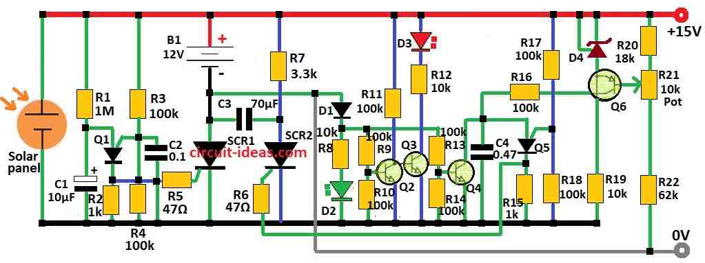
Parts List:
| Category | Item | Quantity |
|---|---|---|
| Resistors (All resistors are 1/4 watt unless specified) | 1M, 3.3k, 18k, 62k | 1 each |
| 100k | 10 | |
| 47Ω | 2 | |
| 10k | 3 | |
| 1k | 2 | |
| Potentiometer 10k | 1 | |
| Capacitors | Electrolytic 10µF 25V | 1 |
| Ceramic 70µF | 1 | |
| Ceramic 0.1µF | 1 | |
| Ceramic 0.47µF | 1 | |
| Semiconductors | IC TL431 | 1 |
| Transistors 2N6027 | 2 | |
| Transistors 2N3904 | 3 | |
| Transistor 2N3906 | 1 | |
| SCRs S2800A | 2 | |
| Diode 1N4148 | 1 | |
| LEDs | LED green 5mm 20mA | 1 |
| LED red 5mm 20mA | 1 | |
| Power Components | Solar panel 7A (up to 100W) | 1 |
| Battery 12V | 1 |
This article show a different way to make solar charger controller.
It uses special kind of switch called force commutated SCR.
Before people mostly used relay or transistor for this job.
But this new design give some good benefits.
Why use SCR design?
Strong and long-lasting: SCRs are very tough and can last long.
Simple: Only one SCR can do 3 jobs like turn ON/OFF the current, stays ON latch, and stop wrong connection means reverse polarity.
How it work:
Main SCR: This part is to control how power goes from solar panel to battery.
Commutation SCR: This second one help turn OFF the main SCR after it is finish.
Control circuit: Made from easy to find parts this circuit uses something called PUTs (programmable unijunction transistors) to manage both SCRs.
Things to remember:
This design is clever but is not best for saving money or energy.
Today the better and cheaper options exist.
Still this circuit is very good for learning how SCRs work and where we can use them.
Circuit Breakdown:
Voltage Reference:
A TL431 chip is used to keep voltage at exact right level.
One transistor checks battery voltage and compare with reference voltage and this help control charging properly.
Commutation Capacitor:
This capacitor is very important as it helps to turn OFF the main SCR.
Its size matters a lot with too small or too big, circuit may not work right.
SCR Turn Off Time:
The design also think about how long SCR takes to turn OFF and this is important for correct working.
Minimum Conduction Period:
Circuit ensures there is enough time for capacitor to charge fully and switch OFF SCR in right way.
Holding Current:
Commutation SCR need certain amount of current to stay on.
Design take care of this so it can turn OFF when needed.
LED Function:
LEDs used to show what is happening in circuit like charging or not charging.
In short this circuit explain clearly how the whole system work step by step.
How to Build:
To build a SCR Based Solar Charger Controller Circuit follow the below mentioned steps :
Components:
- First collect all parts we need like SCRs, resistors, capacitors, transistors, TL431 chip and LEDs.
Circuit Design:
- Use the given details to draw the circuit diagram.
- Put all parts in right place and connect them properly.
PCB Design:
- If we want to make a PCB then design the PCB layout using the circuit diagram.
- We need to know how to use PCB design software for this step.
Component Placement:
- Place all parts on the PCB as per the layout.
- Ensure everything is facing the right way then solder them carefully.
Wiring:
- Use hookup wires to connect parts on PCB if needed.
- Follow circuit diagram closely, wrong wire can stop circuit from working.
- Before turning ON the power check everything again with all parts and connections.
- Use a multimeter to check for short circuits or broken paths.
- Then slowly give power and watch if circuit works correctly.
- If it does not work properly then use basic tricks to find the problem.
- Check each part, wire and signal one by one.
Final Testing:
- When circuit works fine test it fully to ensure it is stable and working with long term.
Note:
- This project need good knowledge in electronics.
- If anyone is not sure how to do it then ask someone with experience for help.
Conclusion:
SCR Based Solar Charger Controller Circuit is strong and honest way to charge battery using solar panel.
With SCRs and smart control parts the circuit manages charging based on battery voltage and other signals.
Even if this method is not most modern but it is still very useful to learn and understand how SCR circuits work.