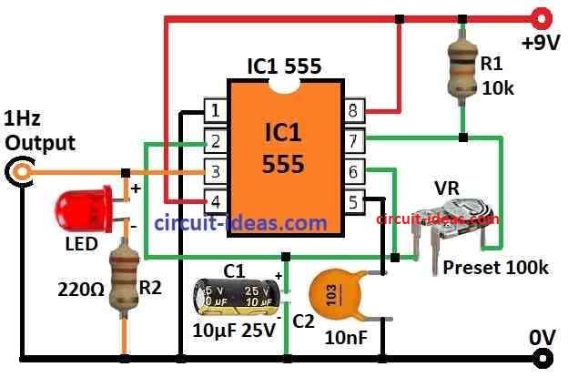
A Simple 1 Hz Pulse Frequency Generator Circuit makes pulse every 1 second look like one pulse in one second.
This circuit are used in many things like clock, timer and signal maker.
Circuit Working:
Parts List:
| Category | Component | Quantity |
|---|---|---|
| Resistors | 10k 1/4 watt | 1 |
| 220Ω 1/4 watt | 1 | |
| Preset 100k | 1 | |
| Capacitors | Ceramic 10nF | 1 |
| Electrolytic 10µF 25V | 1 | |
| Semiconductors | IC 555 | 1 |
| LED any 5mm 20mA | 1 |
This is 1Hz pulse maker circuit using popular 555 timer IC works as astable multivibrator.
LED show the output pulses by blinking ON and OFF.
Astable multivibrator make wave always so it does not need any trigger like monostable type.
That is why it called “free running.”
This circuit is helpful for making clock pulses.
Time for high and low output depend on 2 resistors and 1 capacitor outside the 555 IC.
Clock means wave go high then low again and again.
One high low is one clock cycle.
Clock has frequency and duty cycle.
Frequency means how many cycles in 1 second.
Duty cycle means how long it stay high compare to low.
We can set 555 IC for correct frequency by choosing right resistor and capacitor.
It can also make duty cycle not equal 50%.
Formula is below for how to calculate this.
Capacitor C1 charge to VCC power through resistors R1 and R2.
When charge go more than 2/3 of VCC then comparator 1 give high and flip flop changes and output becomes low.
Then discharge start pin 7 connects to ground so capacitor C1 start to empty through R2.
As capacitor discharge voltage goes down.
When it goes less than 1/3 of VCC comparator 2 go high then flip flop reset and output becomes high.
So output change from low to high and back again.
This happen again and again and hence this makes the pulse.
Formula:
The frequency of 555 timer IC in astable mode can be found using this formula:
Frequency = 1.44 / ((R1 + 2R2) × C1)
where,
- Frequency is how many cycles happen in 1 second it is in Hertz Hz which means more frequency means more cycles per second.
- R1 and R2 are resistors used in timing they are connected to special pins on 555 IC.
- C1 is the capacitor used for timing it is also connected to IC.
- 1.44 is fixed number because of how 555 IC is made inside..
How formula works:
555 IC use R1, R2 and C1 to control how fast it charges and discharges.
This make the output go high and low again and again.
That gives the frequency.
Formula shows how R1, R2 and C1 change the frequency.
Duty Cycle Formula for 555 Timer in Astable Mode:
Duty Cycle = (R1 + R2) × 100 / (R1 + 2R2)
where,
- Duty Cycle is how much time output stays HIGH in one full cycle which is in percent (%).
- 50% duty cycle means output is HIGH half time and LOW half time.
- More than 50% means HIGH time is more.
- Less than 50% means HIGH time is short.
- R1 and R2 are resistors that control timing.
- They are connected to special pins on IC.
How formula works:
R1 and R2 decide how long charging and discharging happens.
This changes the time output which stay HIGH or LOW.
So it changes duty cycle.
Formula gives the answer in percent.
Important Info:
This formula works only for astable mode of 555 IC.
In actual circuit we mostly use only R1 and R2 values to change timing.
Capacitor C1 has small effect.
If circuit needs very correct duty cycle we may need better method or calculation.
Charging Time Constant (Tau) for 555 IC:
τ = R1 × C
here:
- τ (tau) is the charging time constant in seconds.
- R1 is the resistor connected in the circuit.
- C is the capacitor in farads.
This formula tells how fast capacitor charges in the circuit.
Bigger R1 or C means slower charging.
How to Build:
To build a Simple 1 Hz Pulse Frequency Generator Circuit we can follow the below steps:
- Put 555 timer IC on breadboard.
- Connect pin 1 to ground (GND) rail.
- Connect pin 8 to positive (+) rail.
- Take R1 10kΩ and connect one side to pin 7 of IC.
- Take R2 220Ω and connect one side to LED.
- Connect other side of R2 to ground.
- Take C1 10μF and connect positive leg to pin 6 of IC.
- Connect negative leg of C1 to ground.
- Connect another capacitor C2 between pin 5 and ground.
- Connect long leg anode of LED to pin 3 of IC.
- Connect short leg cathode of LED to one side of 220Ω resistor.
- Connect other side of this resistor to ground.
- Connect positive wire of power to positive rail.
- Connect negative wire of power to ground rail.
Testing the Circuit:
- Give power to circuit.
- LED should blink around 1 time per second (1Hz).
- This show 555 IC is giving pulses.
Note:
- Parts and values may change based on what one needs.
- One may need to change resistor or capacitor to get right blink speed or duty cycle.
Conclusion:
Simple 1 Hz Pulse Frequency Generator Circuit is simple but useful circuit it makes pulse every 1 second (1Hz).
This circuit are used in many electronics project where we need correct timing or clock signal.
By using 555 timer IC in astable mode we can make this circuit easy.
We can also change parts to get different frequency if needed.
Leave a Reply