• Skip to primary navigation
  • Skip to main content
  • Skip to primary sidebar

Circuit Ideas for You

Get free circuit ideas online.

  • Home
  • Privacy Policy
  • About
Home » 12V Mini Emergency Light Circuit with LDR

12V Mini Emergency Light Circuit with LDR

Last updated on 12 August 2025 by Admin-Lavi Leave a Comment

12V Mini Emergency Light Circuit with LDR is simple project to make.

Light is ON automatically when dark.

It works with bright white LED and uses 12V battery.

Circuit is good for home, garage and emergency.

Circuit Working:

12V Mini Emergency Light Circuit Diagram with LDR

Parts List:

Component TypeValue Quantity
Resistors10k 1/4 watt1
2.2k 1/4 watt1
33Ω 3 watt1
LDR Standard Light Dependent Resistor1
Preset 50k1
SemiconductorsTransistor BD140 PNP1
Transistor BD139 NPN1
LED 1W High Bright Luxeon White LED1
Switch On/Off Switch1
Battery 12V Battery1

Light changes make circuit work.

LDR checks light level.

During dark time LDR resistance goes high and turns ON transistors and LED glow.

And during light time the LDR resistance goes low and LED is OFF.

VR1 50k set light sensitivity, Q1 BD140 act switch for Q2 and Q2 BD139 gives power to 1W LED.

R3 33Ω limit current and protect LED.

12V battery gives power and S1 switch allows us to ON/OFF manually.

Formulas with Calculations:

BD139 Q2 base current:

IB2 = IC2 / β

where,

  • IC2 is 0.3A
  • β is 50
  • IB2 is 0.3 / 50 = 6mA.

LED current:

VR3 = 12V − 3.5V = 8.5V

ILED = 8.5 / 33Ω = 0.257A (257mA).

Power in R3:

P = I² × R = (0.257²) × 33 = 2.18W

So we used 3W resistor.

How to Build:

To build a 12V Mini Emergency Light Circuit with LDR follow the below mentioned steps for connection and assembling:

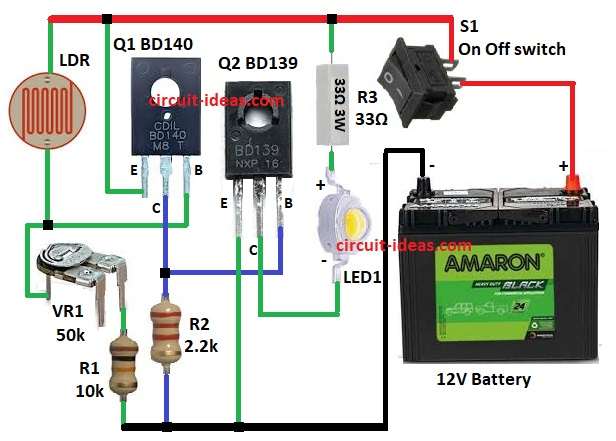
  • Gather all the parts as per circuit diagram above
  • Connect emitter of Q1 to positive supply.
  • Connect base of Q1 between VR1 and LDR.
  • Connect collector of Q1 to junction of R2 and base of Q2.
  • Connect emitter of Q2 to GND.
  • Connect collector of Q2 to LED1 cathode.
  • Connect LED1 anode to one end of R3 and other end of R3 to positive supply.
  • Connect LDR, VR1 and R1 in series from positive supply to GND.
  • Connect S1 switch between +12V battery and positive supply of circuit and connect battery negative to GND.

Conclusion:

12V Mini Emergency Light Circuit with LDR gives bright light in blackout.

Preset VR1 adjusts sensitivity.

Transistors save power and run 1W LED.

Circuit is easy to build, good for home, office and garage.

References:

Datasheet transistor BD140

Datasheet transistor BD139

Filed Under: LDR Circuits, LED and Lamps

About Admin-Lavi

Lavi is a B.Tech electronics engineer with a passion for designing new electronic circuits. Do you have questions regarding the circuit diagrams presented on this blog? Feel free to comment and solve your queries with quick replies

Previous Post: « 12 Watt Audio Amplifier Circuit using IC LF351
Next Post: Magnetic Proximity Switch Sensor Circuit »

Reader Interactions

Leave a Reply Cancel reply

Your email address will not be published. Required fields are marked *

Primary Sidebar


Categories

  • Alarm Circuits (31)
  • Amplifier Circuits (67)
  • Arduino Projects (30)
  • Audio Circuits (93)
  • Automobile Circuits (19)
  • Battery Charger Circuits (48)
  • Free Energy (13)
  • Heater and Temperature Controllers (9)
  • High Voltage (1)
  • Indicator Circuits (38)
  • Inverter Circuits (13)
  • LDR Circuits (14)
  • LED and Lamps (114)
  • Meters and Testers (27)
  • Motor Controllers (18)
  • Oscillator Circuits (32)
  • Power Supply Circuits (91)
  • Remote Control Circuits (6)
  • Security and Protection (23)
  • Sensors and Detectors (74)
  • Solar Circuits (16)
  • Timer Circuits (28)
  • Transistor Circuits (56)
  • Transmitter Circuit (12)
  • Tutorials (4)
  • Water Level Controller (4)

Recent Posts

  • Low Power Led Flasher Circuit using Nand Gate IC
  • Two Star Flasher Circuit with 555 IC
  • Automatic Light Control Switch Circuit using IC 555
  • Ultrasonic Blind Stick Circuit using Arduino
  • Simple Humidity Level Detector Circuit

Recent Comments

  1. Admin-Lavi on Constant Voltage, Constant Current Battery Charger Circuit
  2. Bill on Constant Voltage, Constant Current Battery Charger Circuit
  3. Admin-Lavi on Long Range FM Transmitter Circuit (2km)
  4. Sina on Long Range FM Transmitter Circuit (2km)
  5. Admin-Lavi on Long Range FM Transmitter Circuit (2km)

Copyright © 2025 | New Circuit Ideas