To begin with, this article shows how to make 220V SMPS circuit using one transistor, as the circuit connects to 220V wall socket and it uses only one transistor MJE13005.
Also, it does not need a special IC or many extra parts, instead, it uses a special diode and a transformer coil, so it controls voltage in a different way and prevents it from going too high.
What is a 220V SMPS Circuit:
A 220V SMPS power supply circuit is make for change 220V AC (alternating current) to stable DC (direct current) output.
SMPS circuits are used in many electronic devices like computers, LED drivers and other equipment that provide steady and reliable power.
Circuit Working:
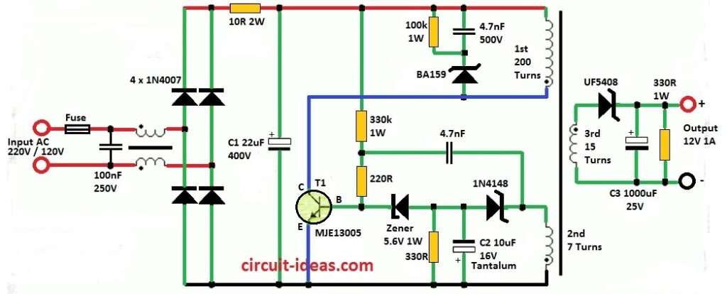
Parts List:
| Components | Values | Quantity |
|---|---|---|
| Resistors (All resistors are 1/4 watt unless specified) | ||
| 10Ω 2W MFR | 1 | |
| 330k 1W MFR | 1 | |
| 220Ω | 1 | |
| 330Ω | 1 | |
| 100k 1W MFR | 1 | |
| 330Ω 1W MFR | 1 | |
| Capacitors | ||
| Electrolytic 22μF 400V | 1 | |
| Electrolytic 1000μF 25V | 1 | |
| Tantalum 10μF 16V | 1 | |
| PPC 4.7nF | 1 | |
| PPC 4.7nF 500V | 1 | |
| PPC 100nF 250V | 1 | |
| Semiconductors | ||
| Diode 1N4007 | 4 | |
| Diode BA159 | 1 | |
| Diode 1N4148 | 1 | |
| Diode UF5408 | 1 | |
| Zener diode 5.6V / 1W | 1 | |
| Transistor MJE13005 | 1 | |
| Fuse | 1 |
Transformer Winding details:
First, use small EE type ferrite core transformer and its middle part (center pillar) size should be 4.5 x 4.5 mm with 0.4 mm air gap and we can take this core from old ATX power supply transformer.
Next, make primary winding and then use 0.12 mm wire and wind 200 turns total.
Start, with 100 turns then put thick insulation after that do another 100 turns same direction to finish first primary.
Now, add third secondary winding and put one more thick insulation layer and then wind auxiliary winding because it has a thin insulation.
Transformer Winding Formula:
For 220V SMPS number of turns in primary (Np) is:
Np = ( Vin(nom) × 108 ) / ( 4 × f × Bmax × Ae )
where:
- Vin(nom) input voltage of 220V RMS.
- f is switching frequency which is normally between 50kHz and 200kHz.
- Bmax is max magnetic flux of core which is usually 1200 to 2000 gauss.
- Ae is cross area of core in cm².
We can find it in core datasheet.
Transistor and Diode Place:
Connect transistor T1 to primary winding and be sure good insulation is there and use Zener diode to control base current of T1.
Also, if output voltage is small like 6V or less then use Schottky diode and for more voltage then use fast diode.
Capacitor Install:
Be careful with polarity when we connect capacitors in circuit and if want to control output voltage not in direct way then C2 is very important for that.
Resistor Connect:
Use correct resistor value when adding resistors and follow circuit instruction.
Insulation Layers:
Use insulation between windings and it helps for safety and stop short circuit.
Output Voltage Set:
We can change output voltage by change number of turns in third secondary winding.
Also, remember diode D1 drop some voltage, so think that when we should calculate the final voltage.
Testing:
Use multimeter to check all wire connection and be sure there is no mistake and turn ON power carefully and watch output voltage it must be correct level.
Heat Sink (Optional):
Also, if we want more power then connect heat sink to transistor T1, it will help to remove heat better.
Transistor Choice:
If MJE13005 not available then choose other transistor with Uce 450V or more and Ucb 800V.
Therefore, good options are: KSC5027, 2SC3150, 2SC3457, 2SC2979, 2SC2866 or BUT11AF these are cheap and easy to find.
Output Voltage Change:
To change output voltage change number of turns in third secondary winding which is around 1.17 turns = 1V change.
Also, remember diode D1 will drop some voltage so include that when we calculate.
Diode Choice:
If the output voltage is low, like 6V or less, use a Schottky diode instead of a normal diode and ensure it is rated at 40V or more.
Caution and Warning:
This circuit is not good for beginners because it uses dangerous high voltage from mains.
Furthermore, be very careful and if design is not correct then high voltage can connect to output and hurt someone.
Also, even if the capacitor is not connected to the mains, it can still hold dangerous voltage.
Do this project only if anyone know the risk and the writer is not responsible for any damage or injury.
Conclusion:
To conclude, if we follow the above steps user can build special and good working self-oscillating circuit.
Hence, this 220V SMPS Circuit using One Transistor give adjustable voltage and there is no need for complex IC or optocoupler.