This 3V LED Driver Circuit using IC LT1937 is small LED driver.
It uses IC LT1937 which can run white LED from only 3V battery.
IC take low voltage and boost up for LED.
Circuit is good for mobile light, small torch, display backlight.
It save power and give stable bright light.
Block Diagram:
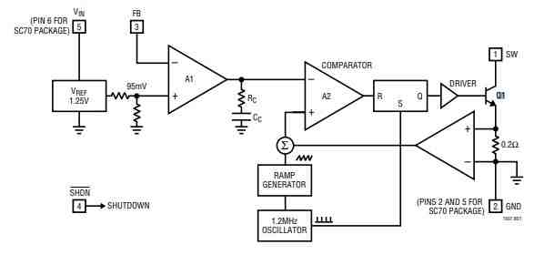
See block diagram to know how circuit works.
LT1937 keep power steady with control.
Switch Q1 turns ON each cycle.
It checks current and add ramp and send to A2.
If signal is big A2 turn OFF the switch.
A2 work with A1 and A1 compare feedback with 95mV.
A1 high means more current out.
A1 low means less current out.
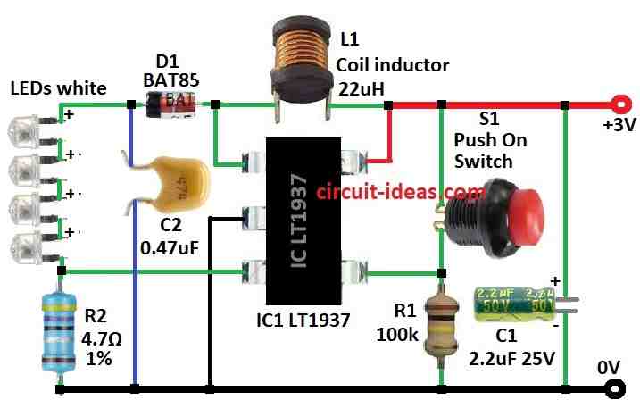
Circuit Description:
Parts List:
| Category | Item | Quantity |
|---|---|---|
| Resistors (All resistors are 1/4 watt unless specified) | 4.7Ω 1% | 1 |
| 100k | 1 | |
| Capacitors | Ceramic 0.47µF | 1 |
| Electrolytic 2.2µF 25V | 1 | |
| Semiconductors | IC LT1937 | 1 |
| Diode BAT85 | 1 | |
| Straw hat white LEDs 5mm | 4 | |
| Coil inductor 20uH | 1 | |
| Push on switch | 1 |
LT1937 can drive 4 LEDs in series from 4.2V battery with 4mA current.
At 4mA there is no pulse so skip if circuit made for 15mA.
If current is low then pulses skip and small ripple come.
Average current is still stable with even near to zero.
Use 22µH inductor for 1.2MHz which is low resistance type.
Use ceramic capacitor X5R or X7R.
Like C1 is 2.2µF input and C2 is 0.47µF output.
Use fast Schottky diode with low voltage drop for less loss.
Big diode capacitance make more switching loss at 1.2MHz.
Best diode rating is 100 to 200mA.
LED current is set by resistor R2.
Formula: Current = 95mV ÷ R1.
Use 1% resistor for accurate LED current.
Formulas and Calculations:
This formula helps set LED current using LT1937 chip.
Main formula:
R2 = 95mV / ILED
This means:
The chip uses a 95mV reference voltage at the ISET pin.
By choosing resistor R2 we can decide how much current flows through LED.
Rearranged formula:
ILED = 95mV / R2
Example:
We want 20mA LED current:
R2 = 0.095V / 0.02A = 4.75Ω
Pick nearby resistor: 4.7Ω or 5.1Ω
Important:
Check resistor power rating:
P = I² × R2
Ensure resistor can handle the heat with 1/4 watt is good for most cases.
Summary:
Use R2 = 95mV / ILED
This sets LED current based on internal 95mV reference of LT1937.
How to Build:
To build a 3V LED Driver Circuit using IC LT1937 follow the below mentioned steps for connection purpose:
- Collect all parts from circuit diagram.
- Give correct voltage for LT1937 for that see the datasheet.
- Connect Wire LT1937, add inductor 22µH, capacitor 2.2µF input + 0.47µF output, Schottky diode, R2 and check its polarity.
- Test the power ON and check output voltage and LED current with load.
- Change resistor or parts if output not stable.
- Use good insulation, grounding and solder neat.
Conclusion:
3V LED Driver Circuit using IC LT1937 is small and is good for powering 3V LEDs from bigger voltage.
This circuit keeps LED bright and steady and is good for many LED projects.