In this tutorial, we will teach how to make a small 5V 1A SMPS Circuit, as this circuit changes AC power to 5V 1 amp because of this maybe many people are looking for this.
The circuit uses one small chip called TNY267P and this chip work like ON/OFF switch and also control the current, it act like tiny power supply inside which does not get too hot and it also make power for itself from main circuit.
All this fit in small box like 555 timer chip.
Hence, TNY267P chip work very fast around 132,000 times in one second and it can handle up to 700 volts.
What is a 5V 1A SMPS Circuit:
This 5V 1A (1000mA) SMPS is a power supply circuit which give max 1 amp current and keep output voltage always 5V stable and controlled.
This kind of power supply mostly powers microcontrollers, small electronic things and low-power devices.
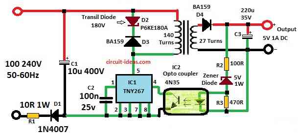
Circuit Working:
Parts List:
| Components | Values | Quantity |
|---|---|---|
| Resistors | 10Ω 1 watt | 1 |
| 100Ω 1/4 watt | 1 | |
| 470Ω 1/4 watt | 1 | |
| Capacitors | Electrolytic 10μF 400V | 1 |
| PPC 100nF 25V | 1 | |
| Electrolytic 220μF 35V | 1 | |
| Semiconductors | Diode 1N4007 | 1 |
| Fast Diode BA159 | 2 | |
| Transil TVS Diode P6KE180A | 1 | |
| Zener Diode 5V 1W | 1 | |
| IC TNY267 | 1 | |
| Opto coupler IC 4N35 | 1 | |
| Transformer | 1 |
This circuit use half wave rectifier because design is simple and power needed is very low.
Next, a 180V rated transil Zener diode blocks voltage spikes or alternatively a parallel resistor and capacitor can be used instead.
Also, for feedback it uses opto coupler.
Furthermore, pick the correct Zener diode (ZD) to set the output voltage, choose a ZD voltage about 1V higher than the desired output to account for the optocoupler LED voltage drop.
Example: If we want 5V output then use 5.6V ZD.
Not only 5V is possible, output voltage can change for that we need to do just two things:
Change secondary coil winding around 1.4 turns per volt and choose ZD with voltage about 1V more than wanted output.
If using this supply for low volt like 5V or less then better to use Schottky diode instead of fast diode it gives better efficiency.
Lastly, when you plug in this power supply and provide a 230V input, it can deliver a maximum output of about 13 watts.
Transformer Building:
This project uses small transformer with ferrite EE core, where middle part of core which is center column is 4.5mm x 4.5mm and it have small air gap of 0.4mm.
Primary side have 140 turns of thin wire which is 0.15mm.
For 5V output secondary side have 27 turns of thicker wire of 0.4mm and because power is low no need to split secondary winding.
How to build transformer:
First, wind all 140 turns of primary winding and be sure layers are neat and connected well.
Put copper tape between primary and secondary as shield and connect tape to cold end of primary, but be careful with no short circuit!
Use strong insulation like 12 layers of duct tape or other strong tape and then wind the 27 turns of secondary wire.
To reduce noise or interference we can add small capacitor around 1nF/Y1 type between primary and secondary.
And for more settings check datasheet of TNY263 or TNY268 series.
Remember:
Higher number in series means more power support.
Newer series like Tiny Switch-III (like TNY274 to TNY280) can give more power and we can use these too and just check the pin connections some may be different.
Safety Caution:
Switching power supply work with high mains voltage which is not safe for beginners and if we do not make the circuit properly, mains voltage can reach the output, which is very dangerous
Even after unplugging from mains the capacitors can still hold big voltage and give shock.
So build and use this circuit at ones own risk and if anything bad happen to health or property author is not responsible.
Transformer Formulas:
Step 1 Find Primary Turns (Np):
Use this formula:
Np = Vin × 108 / (4.44 × f × B × Ac)
where:
- Vin is input voltage in volts
- f is working frequency in Hz
- B is magnetic flux for ferrite which uses around 0.3T
- Ac is core area in square meters
Step 2 Find Secondary Turns (Ns):
Ns = Np × Vout / Vin
where,
- Vout is output voltage in volts.
Step 3 Calculate Output Voltage (Vout):
Vout = VZD + VLED
where,
- VZD is Zener diode voltage
- VLED is voltage drop across opto LED which is usually around 1V
Step 4 Turns per Volt (TpV):
TpV = Ns / Vout
This gives how many turns needed for 1 volt on secondary side.
Choose Zener diode with voltage about 1V more than wanted output voltage to cover LED voltage drop.
Now use TpV to wind correct number of turns on transformer for the output voltage and build the circuit as per diagram.
For better efficiency at 5V or less replace fast diode with Schottky diode and if noise problem happens add noise filter circuit.
Also for safety and isolation we can add a 1nF/Y1 capacitor between primary and secondary side.
Now the simple 5V 1A SMPS circuit is ready to work with 220V or 120V AC.
Note:
If anyone face problem while making this circuit feel free to ask in the comments.
Conclusion:
Overall, we designed this 5V 1A SMPS Circuit with safety, temperature control and proper rules in mind and if we use it for commercial or industrial applications then always follow correct design standards and safety rules.