• Skip to primary navigation
  • Skip to main content
  • Skip to primary sidebar

Circuit Ideas for You

Get free circuit ideas online.

  • Home
  • Privacy Policy
  • About
Home » Simple Audio Level Indicator Circuit using IC LM3915

Simple Audio Level Indicator Circuit using IC LM3915

Last updated on 10 June 2026 by Admin-Lavi Leave a Comment

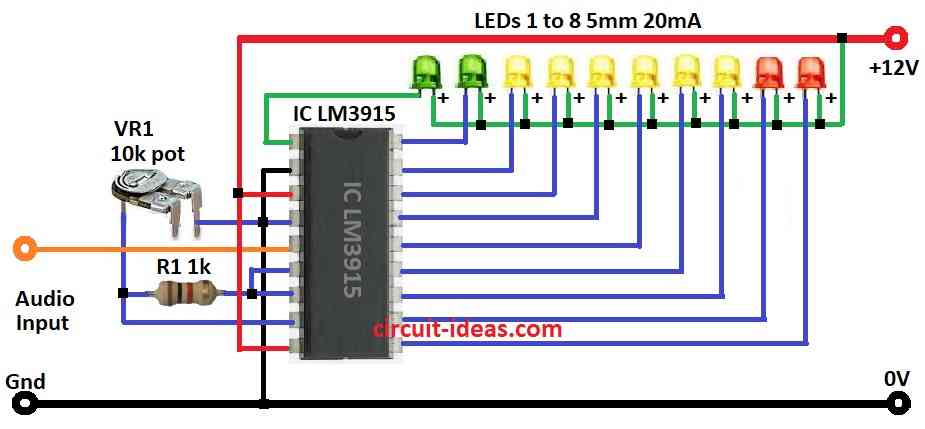
Simple Audio Level Indicator Circuit using IC LM3915 show sound strength with lights, its display driver is good for sound visual circuits.

Also, it takes analog voltage and can light up 10 LEDs, LCDs or other displays in line.

This circuit uses an LED VU meter, which music lovers enjoy because it displays sound levels with LEDs.

The LM3915 IC also makes the LED sound meter easy to build

Circuit Working:

Simple Audio Level Indicator Circuit Diagram using IC LM3915

Parts List:

ComponentsValuesQuantity
Resistor1k 1/4 watt1
Preset 10k1
SemiconductorsIC LM39151
LED Green 5mm 20mA2
LED Yellow 5mm 20mA6
LED Red 5mm 20mA2

To begin with, this above audio level circuit is easy to make; LM3915 chip show sound level like VU meter and also it split audio into 10 parts and compare with inside reference.

Furthermore, it has 10 outputs and each for one LED and voltage divider set level for pins.

Audio signal change to DC and then go through resistor network and if pin voltage is more than reference then that LED turns ON.

Formulas:

When making audio level circuit with LM3915 remember these key formulas:

1. Reference Voltage (Vref):

Set by voltage divider using 10k preset and 1k resistor.

Vref = Vin × (Rpreset / (Rpreset + R1k))

where,

  • Vin is the input voltage from audio
  • Rpreset is the 10k resistor
  • R1k is the 1k resistor

2. LED Current Limiting Resistor RLED:

Use ohms law to find resistor for LED safety:

RLED = (Vsupply − VLED) / ILED

where,

  • Vsupply is the power supply for example 12V
  • VLED is the LED voltage drop to about 2V for red, green and yellow
  • ILED is the LED current which is usually 20mA

3. Segment Reference Voltage (Vi):

Each LED turns ON based on voltage level:

Vi = Vref × i

where,

  • Vi is the voltage for i-th LED
  • i is the LED number from 0 to 10

Use these formulas to build and tune the audio level circuit with LM3915 properly.

How to Build:

To build a Simple Audio Level Indicator Circuit using IC LM3915 follow the connections steps mentioned below:

  • First, collect all parts shown in the circuit diagram.
  • Next, connect pin 1 of LM3915 to cathode of 1st green LED and then keep going with pin 10 to pin 18 connect to rest LEDs with cathode side.
  • After that, connect LED anodes to +12V power supply.
  • Now connect pin 2 of LM3915 to ground and then connect pin 3 and pin 9 to +12V supply.
  • Then connect pin 4 to one leg of preset VR1.
  • Connect pin 5 to audio input and then join pin 6 to pin 7.
  • Also connect one end of resistor R1 to pin 7 and other end to pin 8 and then connect pin 8 to middle leg of preset VR1.

Conclusion:

To conclude, this is easy way to build Simple Audio Level Indicator Circuit using IC LM3915, as it helps see sound level by turning analog audio into blinking LEDs.

References:

Datasheet IC LM3915

Filed Under: Audio Circuits, Hobby Circuits, Indicator Circuits, LED and Lamps, Mini Projects

About Admin-Lavi

Lavi is a B.Tech electronics engineer with a passion for designing new electronic circuits. Do you have questions regarding the circuit diagrams presented on this blog? Feel free to comment and solve your queries with quick replies

Previous Post: « Free Energy From Air Circuit
Next Post: Function Generator Circuit using IC L8038 »

Reader Interactions

Leave a Reply Cancel reply

Your email address will not be published. Required fields are marked *

Primary Sidebar


Categories

  • 555 Timer Projects (128)
  • Alarm Circuits (80)
  • Amplifier Circuits (92)
  • Arduino Projects (103)
  • Audio Circuits (189)
  • Automation Circuits (127)
  • Automobile Circuits (38)
  • Battery Charger Circuits (85)
  • DIY Projects (372)
  • Free Energy (12)
  • Heater and Temperature Controllers (32)
  • High Voltage (23)
  • Hobby Circuits (213)
  • Indicator Circuits (63)
  • Inverter Circuits (18)
  • IoT projects (11)
  • LDR Circuits (46)
  • LED and Lamps (199)
  • Meters and Testers (43)
  • Mini Projects (326)
  • Motor Controllers (25)
  • Oscillator Circuits (64)
  • Power Supply Circuits (228)
  • Radio Frequency (7)
  • Remote Control Circuits (12)
  • Renewable energy (14)
  • Security and Protection (118)
  • Sensors and Detectors (233)
  • Solar Circuits (31)
  • Timer Circuits (62)
  • Transistor Circuits (174)
  • Transmitter Circuit (19)
  • Tutorials (29)
  • Voltage Regulator (38)
  • Water Level Controller (10)

Recent Posts

  • Low Current Controlled Battery Charger Circuit using LM723 IC
  • 741 Op-Amp Treble Booster Circuit
  • Simple Diode and Transistor Based Audio Limiter Circuit
  • Simple 500mW Speaker Driver Circuit
  • Easy DIY LM386 Audio Amplifier Circuit

Recent Comments

  1. Logic OR Gate Circuit using Transistors - Circuit Ideas for You on Automatic Street Light Circuit using LDR
  2. Tony Gallegos on NTC Thermistor Based Temperature to Voltage Converter Circuit
  3. colin on Simple Single Transistor Audio Amplifier Circuit
  4. How to Make a Bird Chirping Noise Easily on Chirping Bird Sound Generator Circuit
  5. Transistor Based Medium Impedance Preamplifier Circuit - Circuit Ideas for You on Low Impedance Input Transistor Preamplifier Circuit

Copyright © 2026 | New Circuit Ideas