This Simple Cell Phone Charger Circuit using 1.5V Battery is one special charger we can take anywhere but there is no need to plug; we can charge phone anytime.
It also uses a standard AA or AAA battery like the one used in TV remotes, inside, it includes a circuit that boosts the weak battery power so it can charge a phone.
But remember one AA or AAA battery not charge phone for long time but just little bit only.
Circuit Working:
Parts List:
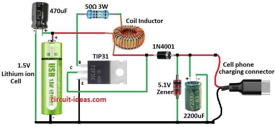
| Components | Values | Quantity |
|---|---|---|
| Resistor | 50Ω 3W | 1 |
| Capacitors | Electrolytic 470µF | 1 |
| Electrolytic 2200µF | 1 | |
| Semiconductors | Transistor TIP31 | 1 |
| Diode 1N4001 | 1 | |
| Zener diode 5.1V | 1 | |
| Coil Inductor | 1 | |
| Cell phone charging connector | 1 |
To charge phone the charger must give more than 4V and max 500mA current and this charger take 1.5V from AA or AAA battery and make it 5V DC which is good for phone charging.
Circuit is simple as it has oscillator, rectifier and voltage regulator which work like “joule thief” type.
There are two coil windings one feedback coil (F) uses 5 turns of 30 wire and other coil (P) use 6 turns of 24 wire.
Furthermore, one 5.1V Zener diode and one big capacitor 2200uF help to keep voltage steady for safe charging; coil winding is not too strict we can try different number of turns and still it will work.
Hence, if charger is not giving power, then try switch wire connection in coil; but remember one small 1.5V battery not strong like phone battery so it can charge only for short time.
Formulas:
This circuit shows how a BJT feedback oscillator works, also it uses a center-tap transformer, so we call it a Colpitts oscillator.
f = 1 / (2 * π * √(L * Ceq))
here,
- f is frequency in hertz Hz how fast it oscillate.
- L is total inductance of transformers main coil in henrys H
- Ceq is like one value from two capacitors C1 and C2
It uses formula:
Ceq = (C1 * C2) / (C1 + C2)
More Information:
Colpitts oscillator use center tap coil to make feedback and this is one type of oscillator; but there are also other types like Hartley and Clapp oscillator.
In actual circuit we must choose between things like how easy to find parts how strong signal is and how steady the frequency stays.
How to Build:
To build a Simple Cell Phone Charger Circuit using 1.5V Battery follow the below mentioned connections steps:
- First, connect battery positive to one side of coil inductor.
- Then connect other side of coil to collector of NPN transistor TIP31.
- Now connect emitter of transistor to negative side of battery.
- Next, connect one diode to collector and the cathode side of diode connects to positive side of phone charging output.
- After that, connect base of transistor to the feedback coil.
- Put one 50 ohm 3 watt resistor between base and battery positive.
- Also, connect one 5.1V Zener diode across the phone charging output to control voltage.
- Add a large 2200µF capacitor across the output terminals where the phone connects.
Important:
- This circuit use high frequency and is not easy to make so if we are not sure how then better learn more first or take help and be careful while building.
Conclusion:
This Simple Cell Phone Charger Circuit using 1.5V Battery is small and easy to carry and is good for charging phone when we are outside or traveling.
Moreover, it uses a boost converter to increase the battery voltage from 1.5V to 5V, which is required for USB phone charging.
Also, this small and useful design is best when no wall plug is nearby and it gives power to keep our phone working and ready to use.
Leave a Reply