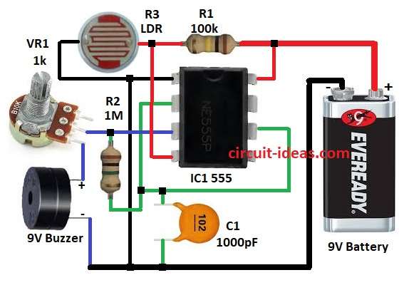
The Simple Dark Sensor Circuit with Buzzer is an easy project to build because it detects the absence of light and activates a buzzer, moreover, users can apply it in night lights, security systems and alarm circuits.
Here, circuit works with LDR, 555 timer and buzzer, as low light makes buzzer ON.
Furthermore, this circuit runs on 9V battery which is small and handy.
Circuit Working:
Parts List:
| Components | Values | Quantity |
|---|---|---|
| Resistors (All resistors are 1/4 watt unless specified) | 100k | 1 |
| 1M | 1 | |
| Potentiometer 1k | 1 | |
| LDR | 1 | |
| Capacitors | Ceramic 1000pF | 1 |
| Semiconductors | IC 555 Timer | 1 |
| Buzzer 9V Buzzer | 1 | |
| Power Supply 9V Battery | 1 |
Simple dark sensor uses IC 555 timer in bistable mode and LDR and resistor R1 make voltage divider for reset pin 4.
When light falls on the LDR, its resistance decreases, which drives the reset pin high and turns the circuit OFF.
However, when darkness increases, the LDR resistance rises, causing the reset pin voltage to drop and turning the buzzer ON.
VR1 pot control current from pin 3 to protect buzzer and then R3 LDR is low resistance in light with 1k to 10kΩ and is high in dark with 100k to 1MΩ.
Hence, this change affects trigger pin 2 to turn circuit ON when dark and then capacitor C1 filter noise and stop false trigger and keep circuit smooth.
Formulas with Calculations:
Voltage divider rule:
V_LDR = 9V × (R2 / (R2 + R3))
where,
- R2 the 1MΩ fixed resistor
- R3 is the LDR resistance change with light.
555 timer trigger voltage:
V_trigger = 9V ÷ 3 = 3V
Timer triggers if pin 2 voltage < 3V.
LDR resistance:
In light LDR is 1kΩ to 10kΩ
In dark LDR is 100kΩ to 1MΩ
Voltage across LDR in light:
If LDR is 10kΩ then,
V_LDR_light = 9V × (1MΩ / (1MΩ + 10kΩ)) = 8.91V
More than 3V the timer will go OFF.
Voltage in dark:
If LDR is 500kΩ then,
V_LDR_dark = 9V × (1MΩ / (1MΩ + 500kΩ)) = 6V
Still above 3V then there is no alarm.
At full dark (LDR = 1MΩ):
V_LDR_dark = 9V × (1MΩ / (1MΩ + 1MΩ)) = 4.5V
Still > 3V then there is no alarm yet, so to activate earlier make R2 smaller so trigger voltage is lower.
How to Build:
To build a Simple Dark Sensor Circuit with Buzzer follow below steps for connection:
- First, pin 1 IC1 connects to GND
- Next, pin 2 IC1 goes to pin 6 IC1
- Then C1 goes between pin 2 IC1 and GN and R2 goes between pin 2 IC1 and pin 3 IC1
- Also, pin 3 IC1 connects to VR1 pot, buzzer and then GND
- Now pin 4 & pin 8 of IC1 connects to +9V battery and also R1 connects between pin 4 and pin 8 IC1
- Finally, LDR R3 connects to one end of +9V battery and other end goes to GND
Conclusion:
Overall, this Simple Dark Sensor Circuit with Buzzer is easy to make and is good to warn in dark, as it change resistors to make more or less sensitive.
Additionally, this circuit operates alarm systems, night lights, and automatic light switches, thereby helping to save energy.