Do we think about screen on calculator or phone if yes ? then a small translator is needed.
Simple Display Driver Circuit is like that translator.
Tiny computer, microcontroller gives it information
Then driver change it to special code for display.
This code tell display which light or pixel should turn ON and to show letter, number or maybe even picture.
So because of this driver circuit we can see nice things on our device screen.
Circuit Working:
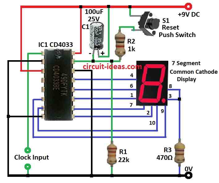
Parts List:
| Category | Component | Quantity |
|---|---|---|
| Resistors | 22k 1/4 watt | 1 |
| 1kΩ 1/4 watt | 1 | |
| 470Ω 1/4 watt | 1 | |
| Capacitor | Electrolytic C1 100µF 25V | 1 |
| Semiconductors | IC CD4033 | 1 |
| Reset Switch | 1 | |
| Display 7-Segment Common Cathode Display | 1 |
This circuit shows how seven segment display work using CD4033 IC.
CD4033 is special chip it counts numbers and also give output for seven segment display.
It changes Johnson code to number on screen.
Display show numbers one by one like 0, 1, 2…
We have used 9V battery DC power to run it.
IC output is connected to common cathode display and model LT543.
If Clock Enable, Strobe and Reset pins are all connected on ground low then IC will keep counting from 0 to 9.
After 9 it will go back to 0 and start again.
But if Reset pin gets high pulse and counting stops and go back to 0.
CD4033 ICs input is very sensitive it start counting when it sees change from high to low signal from positive to negative.
When number increase IC gives correct output to light up display so we can see the number.
Want to count more? Like up to 100 or 1000? Just add more CD4033 chips.
Connect pin 5 carry out of first IC to pin 1 clock input of next IC.
Then when first chip finish 0 to 9 then next chip will start the counting.
We can do this again and again with more chips by counting big numbers easily.
Formula:
Here some important things and formulas we will need when making display driver circuit with CD4033 IC:
1. Clock Frequency:
CD4033 moves to next number when it get clock pulse on CLK pin.
We must choose how fast one wants it to count and this speed is in Hz (Hertz).
To find time between pulses use this formula:
T = 1 / f
where,
- T is time between pulses
- f is frequency we want in Hz
2. Resistor for LED Segments:
Each LED in 7 segment display needs a resistor.
Why? So LED will not get too much current and burn out.
Use ohms law to find resistor value:
R = (VDD − VLED) / ILED
where,
- VDD is the power supply voltage
- VLED is the LED voltage drop which is usually around 2V
- ILED is the current we want for LED which is around 10 to 20 mA is good
3. Debounce Capacitor:
If we use push button to give clock signal it can bounce and give multiple counts fast.
To fix this use a capacitor.
Use this formula to find value:
τ = R × C
- τ is time to remove bounce which is called time constant
- R is resistor value in circuit
- C is capacitor one chooses
Pick C so it stops the bounce but not too slow or button will feel delayed.
Note:
These formulas give basic idea for making CD4033 driver circuit.
But maybe we need to change values a bit which depends on the parts and what we want the circuit to do.
How to Build:
To build a Simple Display Driver Circuit we need to follow the below mentioned steps:
- Take 9V DC battery or power source.
- Connect red wire to positive rail of breadboard and black wire to GND.
- Put CD4033 chip on breadboard.
- Now connect these pins to GND like pin 8, pin 2 and pin 14
- Put common cathode 7segment display on breadboard.
- Connect its common cathode pin to ground.
- Put resistor R3 to limit the current and connect it to segment pins 3 and 8 of display.
- Then connect all other segment pins for matching output pins of CD4033.
- Now connect these control pins of CD4033 like pin 1 (Clock), pin 2 (Clock Enable), pin 3 (Strobe) and pin 15 (Reset)
- We can use push buttons or switches.
- For Enable, Strobe and Reset pins connect them to GND with pull down resistor if not using buttons.
- To count numbers CD4033 need clock pulse at pin 1.
- We can use them as pulse generator or for simple push button one side connected to VDD other to pin 1 with pull down to GND
- Be sure all GND lines are connected together from the power supply, IC, display and buttons.
Test the Circuit:
- Turn ON the power.
- Now press the clock button or give pulse one should see numbers changing on display.
- If it is too fast or slow then adjust the clock speed.
Note:
- This setup is basic.
- We can add more CD4033 ICs to count bigger numbers like 2 digit, 3 digit etc.
- Or we can add more control logic for cool functions.
- Always check CD4033 datasheet for correct pins and details.
Conclusion:
Simple Display Driver Circuit is very important part in electronic devices.
It take input signal and change it into control signal for screen or display.
This help show information in visual way like numbers, letters or pictures.
Because of this display driver is used in many things from small number displays to big graphic screens.