Simple Freezer Alarm with Buzzer Circuit is like small guard for our ice food, it uses one sensor, thermistor to check cold level.
Furthermore, if freezer become warm too much then buzzer makes loud sound to tell us something is not right, like food is going to melt.
Hence, with this indication we can do something fast before the food gets bad.
Circuit Working:
Parts List:
| Components | Values | Quantity |
|---|---|---|
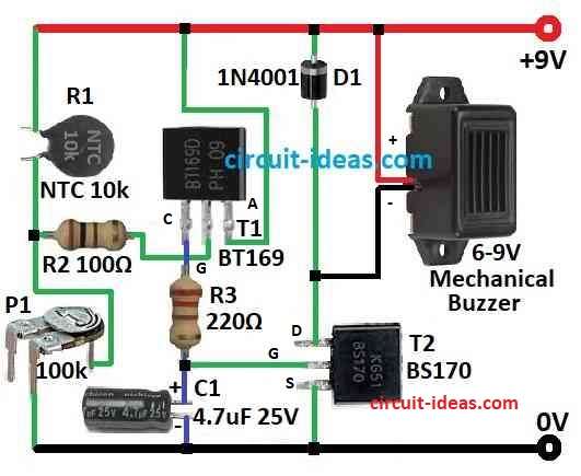
| Resistors | 220Ω 1/4 watt | 1 |
| 100Ω 1/4 watt | 1 | |
| Thermistor NTC 10k | 1 | |
| Preset 100k | 1 | |
| Capacitors | Electrolytic 4.7µF 25V | 1 |
| Semiconductors | SCR BT169 | 1 |
| MOSFET BS170 | 1 | |
| Diode 1N4001 | 1 | |
| Mechanical Buzzer 6-9V | 1 |
This is simple freezer alarm circuit which is very sensitive to make buzzer sound when freezer get too warm, it work with 9V DC power, we can also use normal 9V battery for this.
One small sensor called thermistor R1 NTC type checks the cold inside freezer, also some parts like T1 and T2 transistors help to turn ON the buzzer and the buzzer is normal type which work with 6 to 9V.
If inside freezer become hot then sensor feels it and buzzer start to beep and buzzer keeps beep until we turn OFF the power.
We can use one small switch in power line to turn ON or OFF and also reset the alarm.
How to Build:
To build a Simple Freezer Alarm with Buzzer Circuit follow the below mentioned steps:
- First, put all parts on PCB like shown in circuit diagram.
- Use solder to secure all parts on the PCB and make sure all wires connect securely and firmly.
- Now one side of R1 connects to positive power and other side connects to base of transistor T1.
- After that, collector of T1 connects to base of T2 and emitter of T1 connects to negative power line.
- Also, one side of buzzer connects to collector of T2 and other side connects to positive line but passes through diode 1N4007.
- Use small switch between positive power and collector of T1 as this switch is for ON/OFF and reset.
- Use 9V battery and connect positive to positive power line and negative to negative.
Note:
- After we make the circuit try and test it and then put thermistor in freezer and when freezer get too warm buzzer will make sound.
- Also, if we want buzzer to beep at different temperature then we can change value of R1 or other parts.
Conclusion:
Overall, Simple Freezer Alarm with Buzzer Circuit is helpful and easy circuit, as it indicates us when freezer get too warm so food do not spoil.
Moreover, this circuit is good for home or shop freezer and it also gives peace of mind and we can save money by stopping food waste.
Leave a Reply