
This article for Latch Circuit using Transistors talk about how to make a small electric switch and this switch stay ON even after signal goes OFF.
Also, it does not cost much and is easy to make, as it uses transistor and some other parts.
If someone gives small signal to turn it ON it stay ON and it only turns OFF if other circuit not in this article turn it OFF.
Moreover, electronics people use this kind of switch for many things like to turn light ON and OFF.
What is a Transistor Latch Circuit:
An electric circuit uses two transistors to form a latch when it receives a short positive signal from outside then this is called a transistor latch circuit.
Hence, to stop the latch we can touch transistor base to ground or turn power OFF then ON again.
Circuit Working:
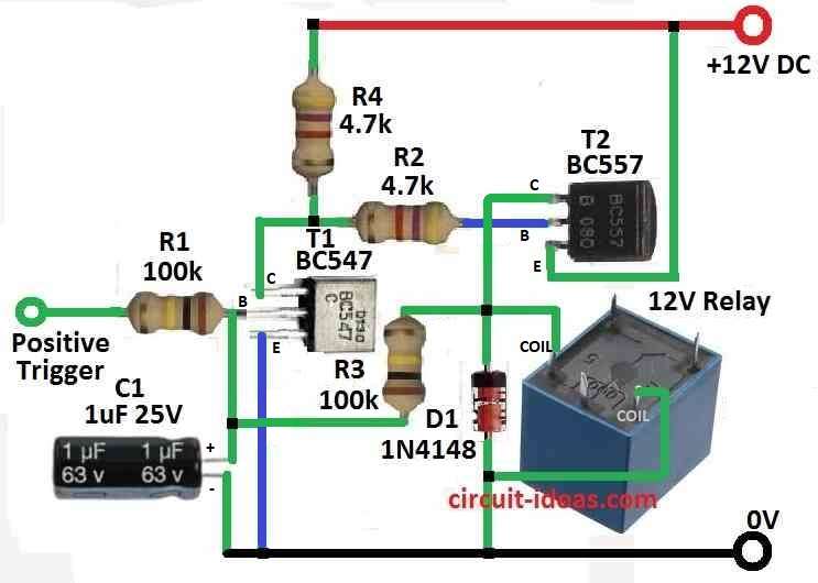
Parts List:
| Components | Values | Quantity |
|---|---|---|
| Resistors | 100k 1/4 W CFR | 2 |
| 4.7k 1/4 W CFR | 2 | |
| Capacitor | Electrolytic 1µF 25V | 1 |
| Semiconductors | Transistor BC547 | 1 |
| Transistor BC557 | 1 | |
| Diode 1N4148 | 1 | |
| Relay 12V | 1 |
In this latch circuit, two transistors T1 and T2, operate together and T2 turns ON or OFF depending on the signal it receives.
Also, T2 works like buffer so it can catch even small signal easily.
But when small positive signal come to input then T1 start to conduct and it pulls base of T2 to ground.
As a result, because of this T2 start working with help of negative voltage from T1.
Furthermore, T2 is PNP type so it works with negative signal and T1 is NPN type which works with positive signal.
Feedback Working:
Important part of this circuit is feedback which helps to latch output fast with normal positive power.
Feedback happen when T2 comes ON after T1 and resistor R3 connect T2s collector to T1s base, and this feedback ensures T1 stays ON after first signal so output stays latched.
Also, capacitor C1 prevents false triggering caused by sudden power ON or external noise.
Reset the Circuit:
To bring circuit back to start just turn power OFF and ON again or press a button to connect T1 base to ground.
Hence, this reset is easy so it is simple to control or change the latch.
Also, this type of transistor latch circuit is useful in alarm or security systems where output need to stay ON after trigger.
Formulas:
The following formulas calculate transistor bias in this circuit:
VBE = 0.7V
This is base to emitter voltage drop, but in forward active mode this voltage of 0.7V drop happen across base emitter of silicon transistor.
So, when we apply voltage to make the base more positive than the emitter for forward bias, the circuit drops about 0.7V at this point.
Also, this voltage drop turns ON the transistor and allows current to flow.
But 0.7V is not always same but in real VBE can change a bit which depend on transistor type, making method and temperature.
Collector Current (IC) = (β + 1) × Base Current (IB)
This formula is for BJT transistor and it tells how base current IB becomes collector current IC.
Here, β (beta) represents the transistors current gain and shows how much the base current amplifies into the collector current.
Like if β = 100 and base current = 1mA then collector current = 100mA.
We write (β + 1) because little current also goes out from base and not only collector.
Also, designers often ignore this small current in basic calculations, but adding +1 makes the result more accurate.
IC = β × IB
This formula is more simple and also used often and it ignore small base current loss and so the collector current is just base current × β.
But if base current changes collector current also changes same way as per gain β.
Which formula to use:
First formula (VBE = 0.7V) is for knowing how much voltage needed to turn ON transistor.
Second formula ((β + 1) × IB) is okay for most simple calculations.
Second and third formulas are for finding collector current from base current.
Third formula (β × IB) is more exact but miss tiny current.
So to make actual circuit better we also need to think about other things like part tolerances and heat change.
How to Build:
To build a Latch Circuit using Transistors following are the below mentioned steps for connections:
Choose and Collect the Parts:
- First collect all parts needed like power supply, NPN and PNP transistors T1 and T2, resistors R1, R2, R3 and capacitor C1.
- Be sure transistor types and resistor values are correct for our design.
Connect Transistors T1 and T2:
- Connect emitter of T1 and T2 to ground.
- Connect T1s collector to positive supply.
- Connect T2s collector to negative supply.
- T1s base should connect to input signal so it gets proper bias.
Set Up Resistors R1, R2 and R3:
- Connect R1 between T1s base and positive supply.
- Connect R2 between T1s emitter and T2s base.
- Connect R3 between T2s collector and T1s base and this makes feedback loop.
Add Capacitor C1:
- Connect capacitor C1 in parallel with resistor R1.
- This helps protect circuit from small noise or sudden triggers when turning ON.
Power Connection:
- Connect power supply to correct places and ensure voltage is within range for our transistors.
Testing and Changes:
- Now give small positive signal to T1s input to start the latch.
- Watch how circuit works.
- If needed change resistor values or other parts to make circuit work better.
Conclusion:
Overall, by following these above steps we can build a Latch Circuit using Transistors, which stays ON after small input signal.
Also, to be sure it works good test everything carefully after building.