In our previous post, we designed a Refrigerator Door Open Alarm Circuit with IC 555 but however, in this post, we design a Simple LDR Based Refrigerator Door Warning Circuit without using any IC.
Moreover, this circuit helps to alert the user when the fridge door stays open for a long time, as this simple circuit which uses an LDR, one transistor, capacitor, a buzzer and a few resistors.
When the refrigerator door opens the inside light falls on the LDR and as a result, the circuit activates the buzzer and gives an alarm sound.
Therefore, it helps save electricity and keeps food fresh by reminding the user to close the door quickly.
Hence, this circuit is simple, low cost and easy to build and also, beginners can make it without much difficulty.
Circuit Working:
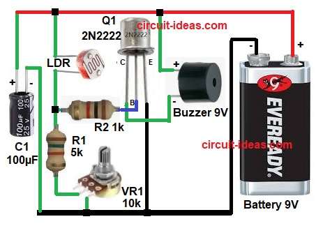
Parts List:
| Components | Values | Quantity |
|---|---|---|
| Resistors | 1k, 5k 1/4 watts | 1 each |
| Potentiometer 10k | 1 | |
| LDR any standard | 1 | |
| Capacitor | Electrolytic 100µF 25V | 1 |
| Transistor 2N2222 NPN | 1 | |
| Buzzer 9V | 1 | |
| Battery 9V | 1 |
First, the LDR senses the light inside the refrigerator and when the refrigerator door remains closed a very little or no light falls on the LDR.
At this time, the LDR resistance stays high, because of this the transistor Q1 2N2222 remains OFF and as a result, the buzzer does not sound.
However, when the door opens the refrigerator lamp turns ON and light falls directly on the LDR then the LDR resistance decreases quickly and consequently, more voltage reaches the base of transistor Q1 through resistor R2.
Now the transistor turns ON and allows current to flow from collector to emitter and as a result, the buzzer gets power from the 9V battery and starts producing sound.
Meanwhile, VR1 helps adjust the sensitivity level, so we can set the exact light level at which the buzzer should turn ON.
In addition, capacitor C1 helps provide a small delay and reduces false triggering caused by sudden light changes.
How to Build:
To build a Simple LDR Based Refrigerator Door Warning Circuit follow the below connection steps:
- First, the circuit starts by gathering all the parts as in diagram above.
- Next, take C1 and connect positive pin to +9V line and negative pin connect to ground line.
- Then take LDR and connect one end of LDR to +9V supply line and connect the second end to junction point of R1 and R2.
- After that take R1 resistor and connect one end to LDR and resistor R2 junction and connect the other end to VR1 upper terminal.
- Then take VR1potentiometer and connect center pin to ground line and connect upper pin to R1 lower terminal.
- After that take R2 and connect one side to LDR and R1 junction and connect the other side to base pin of Q1 transistor.
- Next, take Q1 2N2222 transistor and connect emitter pin to negative or ground line.
Base pin connect to R2 resistor. - And collector pin connect to buzzer negative pin.
- After that, take buzzer and connect positive pin to +9V line and negative pin connect to collector of Q1.
- Lastly take battery 9V and connect positive terminal to positive supply rail and negative terminal connect to bottom ground rail.
Conclusion:
This Simple LDR Based Refrigerator Door Warning Circuit gives an easy and low-cost solution for door open indication.
Moreover, it uses only few components and works well with 9V battery supply and also LDR senses light instantly, so the buzzer gives alert as soon as the fridge door opens.
Therefore, this circuit helps reduce power loss and also protects stored food from spoilage.
Overall, this project is best for beginners, students and simple home automation use.
Leave a Reply