Playing with electric wire is risky especially if we do not know electronics, also wrong use of electricity can be dangerous.
So better to be safe before touching wire and first check if some electricity with leakage voltage is still there.
This article for Simple Non-Contact 220V AC Detector Circuit using IC 555 show how to make an easy circuit using IC 555 and common parts; also this circuit is non-contact 220V AC detector and it help us find live wires easily.
Here, IC 555 works as astable multivibrator which means IC give nonstop pulse output and antenna wire catches electromagnetic field from live wire.
Therefore, small AC current from antenna changes IC pulse little bit and this make LED at output pin blink and by showing voltage is present.
Circuit Working:
Parts List:
| Components | Values | Quantity |
|---|---|---|
| Resistors | 10k 1/4 watt | 1 |
| 220Ω 1/4 watt | 1 | |
| Capacitors | Electrolytic 4.7μF 25V | 1 |
| Semiconductors | IC 555 | 1 |
| LED Any 5mm 20mA | 1 | |
| Antenna | 1 | |
| Battery 9V | 1 |
To begin with, the IC 555 is a popular chip that designers use in many electronics projects and in this circuit, an antenna detects AC voltage, while the IC 555 functions as a voltage comparator.
Furthermore, circuit is simple because it uses main part of IC 555.
When voltage at pin 2 goes below one-third of power then pin 3 turns ON and LED1 lights and when voltage goes higher then output stop and LED1 turns OFF.
Also, pin 2 voltage change because antenna catch AC signal, so LED blink ON and OFF by showing AC voltage is there.
Formulas:
To make astable multivibrator for Non-Contact 220V AC Detector using IC 555 follow this formulas:
Find Frequency:
Use this formula:
f = 1.44 / (R1 + 2 × R2) × C
This gives how fast IC 555 output pulse comes as it affects how sensitive the circuit is.
Find Duty Cycle:
Use this formula:
Duty Cycle = (R1 + R2) / (R1 + 2 × R2) × 100%
This tells how long output stay ON or OFF as it changes how strong the signal is.
Tips:
Change R1, R2 and C values to get best sensitivity, circuit must be safe and it should detect AC voltage without touching wires.
Also, choose right parts and by using these formulas we can build good working circuit with IC 555 for non-contact AC detector.
Hence, change parts value as per our need.
How to Build:
To build a Simple Non-Contact 220V AC Detector using IC 555 follow the below mentioned steps for connections:
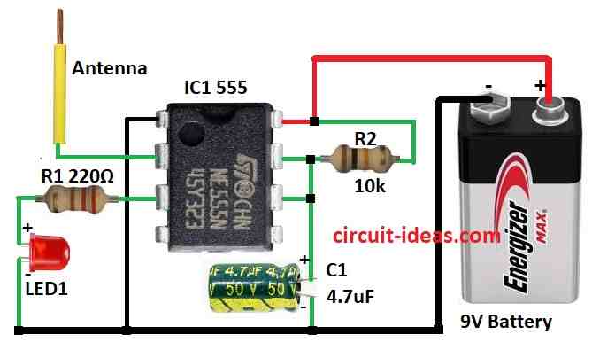
- First, join pin 1 of IC 555 to ground.
- Next, pin 2 goes to antenna.
- After that, pin 3 goes to ground through R1 and LED1.
- Then join pin 6 and pin 7 together and put capacitor C1 from pin 6 and 7 to ground.
- Pin 7 connect to +9V through resistor R2.
- Pin 8 connect to +9V battery.
Notes:
- This circuit does not check voltage amount, it only sense if AC voltage is there.
- Antenna size, part values and distance from wire affect how well it works and is not always reliable.
- Do not use this as real voltage tester as it is for learning purpose only and be careful with AC power and follow safety first.
Safety Tips:
- This is not a real voltage tester and it can not tell exact voltage or if wire is safe.
- Do not use this to check if we can touch a wire, so for safe and correct AC check use proper voltage tester with probe.
Conclusion:
To conclude, this Simple Non-Contact 220V AC Detector Circuit using IC 555 helps learn how antenna can sense AC power; but it is not good for real use because of safety and accuracy problems.
Therefore, use 555 for learning only and for real AC checking and always use good quality tester with probe.
Leave a Reply