Imagine small suns making light in our garden at night.
This Outdoor Garden Solar Lights Circuit works like small power house for our garden flowers.
In daytime solar panel take sun energy and put it in battery.
Then night time come smart circuit take that energy and make LED light ON so our garden stay bright whole night.
Circuit Working:
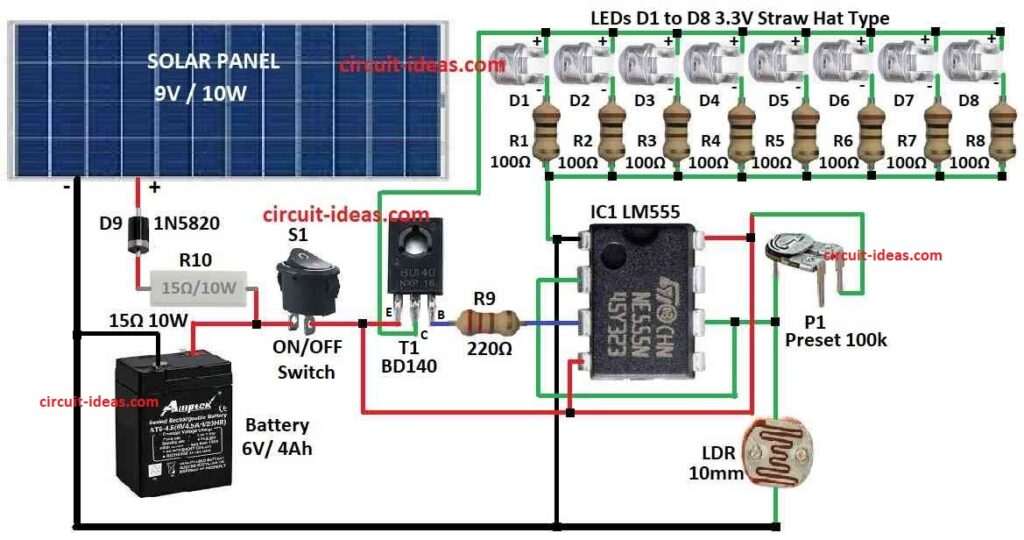
Parts List:
| Component Type | Component Details | Quantity |
|---|---|---|
| Resistors (All resistors are 1/4 watt unless specified) | 100Ω | 8 |
| 15Ω 10W | 1 | |
| 220Ω | 1 | |
| Preset 100k | 1 | |
| LDR100mm | 1 | |
| Semiconductors | IC LM555 | 1 |
| Transistor BD140 | 1 | |
| LEDs White 3.3V Straw Hat Type | 8 | |
| Diode 1N5820 | 1 | |
| Switch ON/OFF | 1 | |
| Solar Panel 9V 10W | 1 | |
| Battery 6V 4Ah | 1 |
This project make automatic garden light using LDR and solar panel to 9V 10W type.
In daytime solar panel gives power to charge 6V 4Ah battery the power goes through diode for right direction and resistor to stop too much current.
When there is enough sunlight one transistor T1 stay OFF because IC LM555 tell it to stay OFF
This IC work like small driver and it can get signal from light sensor which is from 10mm LDR to check how much light it gets from outside.
We can use trimpot multi turn type to set how much light is needed to turn lights ON.
When it starts getting dark transistor T1 turn ON and then LEDs D1 to D8 white straw hat 3.3V type start glowing.
Each LED have resistor R1 to R8 to control how much current goes to it.
When sun come back and light is bright again circuit goes back to OFF mode and lights stop glowing.
To build it put all parts on general PCB and cover with clear plastic box.
Make holes in top of box to fit solar panel and LDR and also make front hole for power switch and trimpot.
Stick battery inside box using double side tape or foam.
Be sure LDR does not get direct sun and put it on top side of box facing south.
This is simple project and we can change or add more things easily.
Like use 6V relay with T1 to control more LED lights if we want.
Formulas:
We make outdoor garden light circuit using solar panel, battery, LEDs, LDR and some other small parts.
Main idea is to use LM555 timer IC to control lights as it checks light level using LDR.
When it get dark the LEDs turn ON.
LED Current Limiting Resistor:
To find resistor value for each LED if we connect in parallel use this easy formula:
R = (Vbattery – VLED) / ILED
where:
- Vbattery is 6V
- VLED is 3.3V which is the forward voltage of LED
- ILED is how much current we want for LED which should be around 20mA or 0.02A
This formula help choose right resistor to stop too much current in LED.
With this setup we can get automatic garden light system that turn ON at night and OFF during day.
How to Build:
To build a Outdoor Garden Solar Lights Circuit we need to follow the below mentioned connections steps:
- Connect plus (+) wire of solar panel to plus (+) side of battery.
- Connect minus (–) wire of solar panel to striped side cathode of diode D9.
- Other side of diode anode connects to minus (–) side of battery as this will stop power from going back to panel.
- Wire LM555 timer IC like inverter driver and check LM555 datasheet for pins and setup.
- Connect output pin of LM555 to base of transistor T1.
- Emitter of T1 connects to minus (–) of battery.
- Collector of T1 connects to LED string D1 to D8
- Put LDR on top of box and face it south so it can see daylight but not direct sun.
- One side of LDR connects to plus (+) of battery.
- Other side connects to inverting input pin of LM555.
- Also connect trimpot P1 from plus (+) of battery to same LM555 inverting pin.
- Turn P1 to change how sensitive light detection is.
- Connect plus side of anode to each LED from D1 to D8 to collector of T1.
- Minus side cathode of each LED connect to one resistor R1 to R8.
- Other side of each resistor connects to minus (–) of battery.
- This way each LED get limited current.
- Put circuit on general PCB board.
- Fix everything inside with clear plastic box.
- Drill holes on top for solar panel and LDR and drill front holes for power switch S1 and trimpot P1.
- Use double side tape or foam to stick battery inside box so it may not move.
- Try the circuit in place where light go up and down.
- Check if LEDs turn ON when light is low and turn OFF when light is bright again.
Note:
- We can change value of resistors and number of LEDs and type of transistor if we want more or less brightness.
- Choose parts depending on how much light and power we need.
Conclusion:
Outdoor garden solar light circuit uses sun power to turn ON LED lights.
It gives easy and eco-friendly light for outside places.
This circuit have solar panel, rechargeable battery, charge controller, driver circuit or inverter and LED lights.
All parts are kept safe inside weatherproof box.
At night it gives light using stored energy which saves electricity and help nature too.