This Simple Over-Temperature Warning Indicator Circuit uses an LED to indicate excessive temperature, as it uses only a few easily available components, making the circuit simple, low cost, and easy to build.
The circuit turns ON an LED when temperature rises above a set level like 45°C – 55°C and therefore, it is useful for basic thermal warning.
Power supplies, chargers and many small electronic projects use this circuit.
Circuit Working:
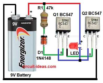
| Components | Values | Quantity |
|---|---|---|
| Resistor | 10k to 47k | 1 |
| Semiconductors | Transistor NPN BC547 | 2 |
| Diode 1N4148 | 1 | |
| Red LED | 1 | |
| Battery 9V DC | 1 |
To begin with, the main purpose of this circuit is to detect the excess heat.
Initially, when the temperature is low, at this time the diode D1 does not conduct properly.
So base current to transistor Q1 is very small, as a result transistor Q1 remains OFF and because Q1 is OFF and Q2 is also OFF, LED does not glow.
Now temperature increases and diode D1 is temperature sensitive.
When temperature rises its forward voltage drops and so more current flows through R1.
D1 then this current goes into the base of Q1 and therefore, Q1 turns ON.
Once Q1 turns ON it provides base current to Q2 and thus, Q2 also turns ON and when Q2 turns ON then current flows through LED and finally, LED glows and gives over-temperature indication.
So the circuit works as a simple heat detector.
How to Build:
To build a Simple Over-Temperature Warning Indicator Circuit follow the below steps for connection:
- First, start the circuit by collecting all the circuit parts as shown in diagram above.
- Then, start with 9V battery positive terminal goes to positive supply rail and negative terminal goes to common ground.
- After that, resistor R1 one end connects to positive supply and other end connects to cathode of diode D1.
- Now diode D1cathode connects to R1 and anode connects to base of transistor Q1.
- Further, transistor Q1 base pin connects to diode D1 anode, emitter pin connects to base of transistor Q2 and collector connected between collector of Q2 transistor and LED
- Transistor Q2 base connects to emitter of Q1, emitter connects to ground and collector connects to between collector of Q1 and LED.
- Lastly, LED anode connects to positive supply and cathode connects to collector of Q1 and Q2 transistors.
Note:
- In this circuit the LED started glowing at 37 degree Celsius and at 47 degree Celsius the LED became very bright.
- Temperature should not go above 60 degree Celsius.
- Further, above this the current through LED will become very high and because of this, the diode will get overheat and may get damage.
Conclusion:
Overall, this Simple Over-Temperature Warning Indicator Circuit using LED is very useful, as the circuit is very easy to understand and it is also easy to build.
Furthermore, it uses only few circuit components and all components are easily available in the market.
When temperature increases an LED turns ON fast and so it gives quick visual warning and because of this, the circuit is good for beginners and it is also good for basic safety use.

Leave a Reply