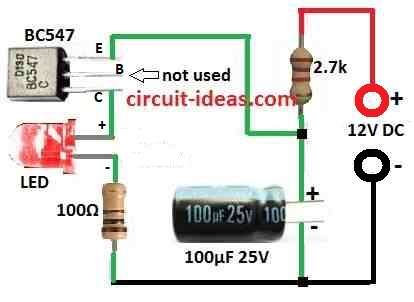
This Simple Single Transistor LED Flasher Circuit show smallest LED flasher circuit ever made.
LED blink ON and OFF again and again by using only one transistor, one resistor and one capacitor.
Just think of only one transistor and some easy parts and LED will start flashing, look nice!
This is type of circuit one would like to try.
This article talk about a very simple LED flasher circuit using only one transistor.
What is a Single Transistor LED Flasher Circuit:
This single transistor LED flasher circuit is very simple as it uses only one transistor to make LED turn ON and OFF.
Circuit is easy to build and people use it for blinking light and for shows or decoration.
Circuit Working:

Parts List:
| Type | Specification | Quantity |
|---|---|---|
| Resistors | 2.7k | 1 |
| 100Ω | 1 | |
| Capacitor | 100µF 25V | 1 |
| Semiconductors | Transistor BC547 | 1 |
| LED Any type any color | 1 |
In 2006 we tried to make very small motorbike flasher but that time we found it something very interesting.
Long time ago Dick Cappels also tried a similar idea.
He followed the work of Leo Esaki who has won a Nobel Prize and made tunnel diode.
The circuit above shows it possible to build working LED flasher with only one transistor.
It looked impossible but it did work!
We do not know before but this work because transistor have special thing called negative resistance.
This is how circuit blink smart way.
We talk more about this and other cool ideas in future article.
We can change blinking speed by changing 2.7k resistor or 100µF capacitor or change both.
But remember voltage must stay over 9V or circuit will not work right.
Formulas:
Here is formula for simple one transistor LED flasher circuit:
Resistor R1 100Ω in series with LED:
This resistor stop too much current so LED does not get burn.
We have used ohms law to find good value for R1:
R1 = (Vsupply – Vf) / Iled
where:
- Vsupply is power voltage and in this circuit it is 12V
- Vf is LED forward voltage which is around 1.8V to 2.2V for red LED
- Iled is how much current LED needs which is around 15mA to 20mA for normal LED
How to Build:
To build a Simple Single Transistor LED Flasher Circuit follow the below mentioned steps:
- Take all needed parts BC547 transistor, 100Ω resistor, 2.7k resistor, one capacitor 100µF to 470µF and any LED we like.
- Now connect all parts like in circuit diagram.
- Be sure LED, transistor and capacitor are connected correct way as they are polarized.
- To change how fast LED blink try different values for 2.7k resistor and 100µF capacitor.
- Power supply must stay above 9V, because if it goes low the circuit will not work.
Testing:
- Turn ON the circuit and check the LED will start blinking.
- If not blinking then make small changes to get good blinking.
Note:
- With only one transistor this circuit uses smart transistor trick to make LED blink.
- Very cool way to see how small parts can do big job.
- Stay tuned and get the blinking effect.
Leave a Reply