Like human plant also need water to stay strong and healthy!
Sometimes it little is hard to know when plant need water.
This Simple Soil Dryness Detector Circuit tell how to make soil moisture sensor.
When soil goes dry and plant need water this device will give an alert.
This article also gives an easy formula to help make the circuit.
What is a Soil Dryness Detector Circuit:
Main purpose of this Simple Soil Dryness Detector Circuit is to check soil is wet or dry by seeing how much moisture is in the soil.
This type of circuit is mostly used in garden and farming to watch water system and to be sure plant are getting enough water.
Circuit Overview:
This smart soil dryness detector circuit uses two NPN transistors which work like switch and one buzzer.
It really show when there is no water in the soil.
Other things like metal or nails also can work good for checking the moisture.
This circuit uses copper wire with no plastic cover for sensing.
Circuit Working:
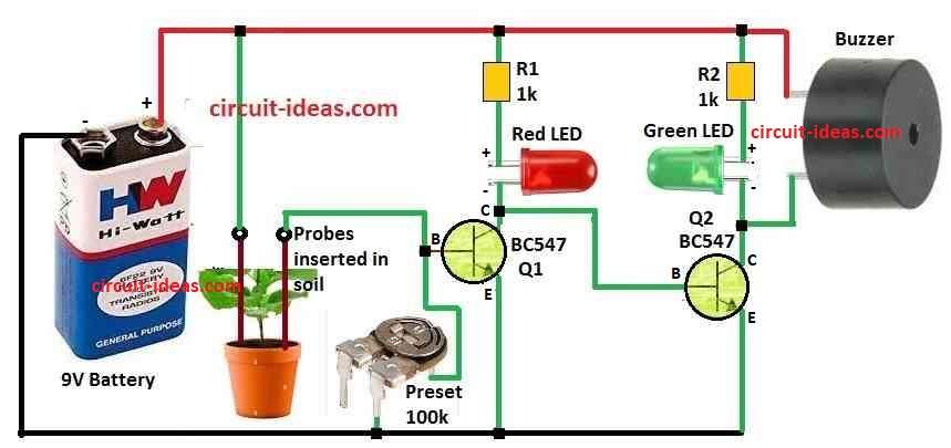
Parts List:
| Type | Component | Quantity |
|---|---|---|
| Resistors | 1k 1/4 W | 2 |
| Preset 100k | 1 | |
| Semiconductors | Transistors BC547 | 2 |
| Red 20mA 5mm | 1 | |
| Green 20mA 5mm | 1 | |
| Aluminum Probes | 2 | |
| Power Source 9V Battery PP3 | 1 | |
| Audio Device Buzzer | 1 |
Circuit get power from 9V battery and this power connects to all parts of the circuit.
Two copper wires without cover or other sensor are put inside the soil.
These wires check if soil have water or not.
If soil is dry and sensor does not find water then Q1 stays OFF.
Then current connects from Q1 collector to base of Q2.
This make Q2 turn ON.
When Q2 is ON then buzzer makes beep sound.
This beep means soil is dry and need water.
LED lights are also added for fast sign.
If soil have good water then green LED turn ON and if soil is dry then red LED blinks.
Sensor wires or other material help to check water in soil.
When soil is wet Q1 turn ON and stops current going to Q2 so buzzer stays OFF.
But when soil is dry Q1 stays OFF and sends current to Q2 which make buzzer beep and red LED blink to show no water.
Formulas with Calculations:
Here is the formula for Simple Soil Dryness Detector Circuit:
We can calculate sensitivity of S by using this formula:
S = R2 / (R1 + Preset)
where:
- S is sensitivity
- R2 is sensor resistance
- R1 is fixed resistor with 100k variable resistor preset)
Steps to calculate:
Put values in formula:
S = (1kΩ) / (1kΩ + 100kΩ)
Now solve:
S = 1 / 101
So S = 0.0099
This mean sensor change 0.0099 when resistance change 1 ohm.
Sometimes S is written as voltage per ohm (V/Ω) or current per ohm (A/Ω).
That means sensor gives small voltage or current change for each ohm in resistance.
But for real sensors this does not always stay same but sometimes it changes.
So this value only is good for basic idea.
Important Note:
We think sensor resistance R2 and output signal change the same way.
But in some cases it does not always happen because which this can make small problem in calculation.
How to Build:
To build a Simple Soil Dryness Detector Circuit follow the below connection steps:
- Put two copper wires without cover or other sensor in soil where we want to check for water.
- Be sure they are not too close, so no wrong signal happen by touching.
- Give 9V battery power to both transistor switch and moisture sensor circuit.
- Connect one wire from sensor to base of Q1 transistor.
- Use 100k preset to set how sensitive the sensor is.
- If soil have water then Q1 will turn ON and let positive current go.
- If soil is dry then Q1 will stay OFF and then bias connects through Q1 collector and turn ON Q2.
- Q2 ON means buzzer start beep sound to show soil is dry.
- When soil is wet green LED will turn ON and if soil dry then red LED will blink.
Conclusion:
This Simple Soil Dryness Detector Circuit is very helpful for taking care of plants and saving water.
It gives actual time signal about how much water is in soil so people know when to give water.
This will stop giving too much or too little water.
References:
DESIGN AND DEVELOPMENT OF SOIL MOISTURE SENSOR AND RESPONSE MONITORING SYSTEM
Design and Implementation of a Soil Moisture Detection system