Simple Solar Garden Light Circuit using One Transistor, one special switch and a sun power to turn on LED at night.
When sun goes down the light turns ON by itself.
And when sun come back the light turns OFF, like a magic!
Circuit Working:
Parts List:
| Category | Description | Quantity |
|---|---|---|
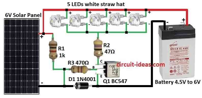
| Resistors | 1k, 47Ω, 470Ω (1/4 watt each) | 1 each |
| Semiconductors | Transistor BC547 | 1 |
| Diode 1N4001 | 1 | |
| LEDs white straw hat 5mm, 20mA | 5 | |
| Solar panel 6V | 1 | |
| Battery 4.5V to 6V | 1 |
This project make night light.
LED turn ON when its dark and turns OFF when its day.
Solar panel control LED with its voltage.
Daytime the sunlight hits the panel and LED stays OFF
And at nighttime there is no sunlight then LED turns ON.
Do not put LEDs in parallel unless there is same brightness.
If LED is dim then use different circuit.
Charging time depend on battery size and panel power.
600mAh + 0.5w panel = 6 to 8 hours charge.
1800mAh + 1w panel = up to 2 days.
47 ohm resistor may need to be change based on battery and LED count.
This explanation shows like battery gets empty every night.
Formulas:
Ohms Law help find resistor R2 value to control LED current:
Formula:
R = V / I
where:
- R is the resistance in ohms Ω
- V is the voltage across resistor
- I is the current through resistor in amps
To find R2 we need:
LED forward voltage (Vf): From LED datasheet.
Number of LEDs in series (Ns): Multiply Vf × Ns
Desired LED current (Id): From datasheet.
Example: White LED = 20mA or 0.02A
Use this details in formula to get correct R2 value.
How to Build:
To build a Simple Solar Garden Light Circuit using One Transistor follow the below mentioned steps for components connections:
- Connect 6V solar panel with one side to positive and other side to negative.
- Transistor Q1 collector goes to resistor R2, base goes to resistor R3 and emitter goes to ground.
- Battery 4.5V to 6V connect positive to positive and negative to negative.
- 5 white straw hat LEDs connect one side to positive and other side to R2.
- Diode D1 connect from battery negative to solar panel negative.
Safety Tip:
- Check there should be no short circuit!
- Check wire before powering ON the circuit which can damage parts or heat too much.
Conclusion:
This Simple Solar Garden Light Circuit using One Transistor is cheap and easy.
This circuit is goes auto ON at night this is because it uses sun power.
While making the circuit stay safe and enjoy our own green garden light!
References:
Can you explain how the following garden solar light circuit works?
Good afternoon firstly thank you for the above Simple Solar Garden Light Circuit using One Transistor. As a first timer to electronics i have been looking for something like this. I have a solar garden light that my daughter bought me but it is not solar and has 3 candles that are each lit by x3 1.5v batteries. As you can guess this has become quite expensive buying batteries so i’d like to convert it to a solar light that i can run all 3 candles (one LED per candle) off of the above circuit. However i have all of the components but i’m confused how the circuit diagram would look on a homemade circuit board. Could you help me with this please. Accept if this is to much to ask?
Hi Kevan, thanks for your question.
Are you looking for the complete schematic that would integrate all the 3 candles with the above circuit?
If yes, then I can certainly help you…