
This easy to build Tachometer Circuit is a small DIY tool to check speed of rotating shaft or disc; we used tachometer to know how fast shaft or wheel spin in RPS (revolutions per second).
Furthermore, this simple circuit uses two 7-segment displays and one slotted opto sensor MOC7811 where all parts are easy to find.
Hence, with this circuit we can measure RPS of rotating shaft or disc and if we add one more counter stage it can count from 00 to 99 RPS.
What is a Sensor IC MOC7811?
The MOC7811 is an opto-slotted coupler, also called an opto-interrupter, it is a useful device in electronics and communication applications.
Moreover, it has two parts: one infrared LED (IRED) and one phototransistor which together they work strong, also its smart design help to detect object or block in light path.
So IC MOC7811 is flexible and popular an people use it for object sensing, position check and rotation count.
Circuit Working:
Parts List:
| Components | Values | Quantity |
|---|---|---|
| Resistors (All resistors are 1/4 watt unless specified) | 8.2k | 1 |
| 220Ω | 1 | |
| 220k | 1 | |
| 1k | 2 | |
| 470Ω | 2 | |
| Potentiometer 4.7k | 1 | |
| Capacitors | Ceramic 0.01μF | 1 |
| Electrolytic 100μF 25V | 1 | |
| Semiconductors | IC1 555 | 1 |
| IC2 7811 | 1 | |
| IC3 CD4081 | 1 | |
| IC4 CD4069 | 1 | |
| IC5 CD4033 | 1 | |
| IC6 CD4033 | 1 | |
| Displays 7 segment common cathode | 2 | |
| LED1 green 5mm 20mA | 1 | |
| ON/OFF switch | 1 | |
| Push to ON switch | 1 | |
| 9V Battery | 1 |
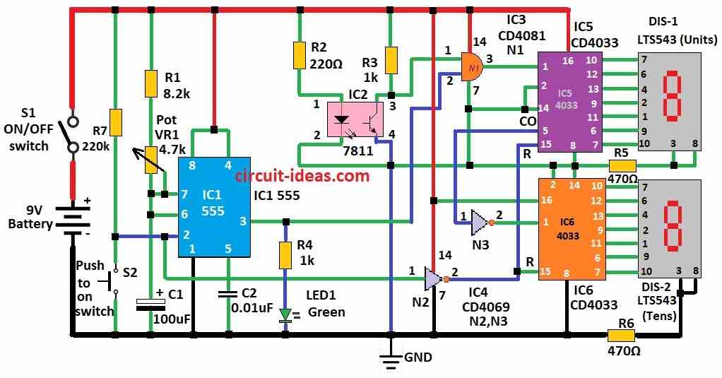
To begin with, this circuit uses many ICs to make tachometer for measuring RPS (rotations per second).
Working parts:
IC 555:
IC 555 Works like monostable timer, when press switch S2 it gives time pulse and LED1 green shows this timing.
MOC7811 IC2:
The MOC7811 (IC2) contains an IR emitter and a photodiode and when an object blocks the IR light, the photodiode changes its output signal.
AND Gate N1:
AND Gate N1 this gate control the CD 4033 counter.
CD 4033:
CD 4033 is decade counter and it sends signal to 7-segment display LTS543 to show RPS and this design can show RPS from 00 to 99.
Two decade counters and displays image:
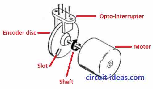
Information also tell us how to make rotating interrupter, as it says to measure slot size of MOC7811 and shaft nose size carefully.
When shaft nose block IR light then it count as one rotation and total counts during sensing time give RPS and also to get RPM it just multiply RPS by 60.
Formulas:
Using the ICs and components listed above, we can build a tachometer to measure the speed (RPM) of a rotating object, such as a motor or an engine.
Subsequently, the tachometer displays the RPM reading on a 7-segment display.
Important Points:
Convert Frequency to RPM:
Use formula:
RPM = f × 60 / PPR
where:
- f is the frequency pulses per second
- PPR is the pulses per one full turn of revolution from sensor
IC 555 as Monostable:
The IC 555 timer generates a single output pulse in response to a trigger signal, hence, this operating mode is called the monostable or one-shot, mode.
Pulse Time T:
Pulse time set by R1 and C1:
T = 1.1 × R1 × C1
where:
- T is the time in seconds
- R1 is the resistance in ohms Ω
- C1 is the capacitor in farads F
Therefore, by using these steps and changing values as needed we can build tachometer for our project.
Safety Measure:
- First, check all wire and parts before turning ON and then follow circuit diagram correctly.
- Before operation, securely fasten the shaft and interrupter to prevent them from falling off or causing a danger.
- When circuit is running keep hands and things away from moving parts and if using for long time better to put circuit in safe box to stop an accident.
Conclusion:
To conclude, with this Tachometer Circuit we can make tachometer to measure spin speed using easy parts; also making this can be fun for electronics hobby; but if we need more features or special output then circuit can get more difficult.