Simple Temperature Controlled DC Fan Circuit is like smart fan.
It use special sensor to feel heat around.
When place get too hot then circuit makes fan run fast like turning AC high.
If the place cools again then fan slow down or stop to save power.
This circuit uses parts like thermistor which change with temperature and control part to do all this by itself.
So the electronics stay cool and works good.
Circuit Working:
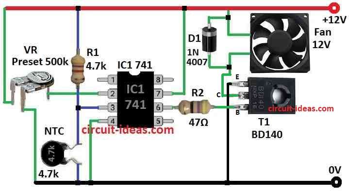
Parts List:
| Category | Component | Quantity |
|---|---|---|
| Resistors | 4.7k 1/4 watt | 1 |
| 47Ω 1/4 watt | 1 | |
| Preset 500k | 1 | |
| NTC Thermistor 4.7k | 1 | |
| Semiconductors | IC 741 | 1 |
| Transistor BD140 | 1 | |
| Diode 1N4007 | 1 | |
| Fan 12V | 1 |
This circuit is made to cool down electronic things that get hot.
It turns ON DC fan when nearby temperature go above set level.
When temperature go back normal fan turns OFF by itself.
Fan used is small 12V DC brushless fan like in computer.
Circuit use thermistor which is a resistor that change its resistance with heat.
There are two types of thermistors: NTC (Negative Temperature Coefficient) and PTC (Positive Temperature Coefficient).
NTC type the resistance go down when temperature go up.
PTC type the resistance go up when temperature go up.
Thermistors come in many values like 100 ohms to 10k and more.
In this circuit it is 4.7k ohm NTC thermistor.
IC 741 work like voltage checker comparator to control the fan.
Pin 2 minus input get voltage from VR adjustable one.
Pin 3 plus input get voltage from R1 and thermistor as they work like divider.
So voltage at pin 3 change based on thermistor resistance.
If temperature is normal and is set by VR then voltage at pin 3 is more than pin 2 and then IC output will go high.
When output high transistor T1 stay OFF because base get positive then fan wont work
But if temperature go higher then thermistor resistance goes down and this make voltage at pin 3 go low.
Now IC output goes low when turn ON transistor T1 then fan start to spin and make air flow.
When temperature come back to normal then fan stops again.
Diode 1N4007 is important as it removes back EMF when T1 turn OFF so no damage happen.
Formulas:
Simple Rules and Formulas for Making Temperature Controlled DC Fan Circuit Using IC 741 Comparator
Voltage Divider Output goes to Pin 3 of IC 741 Non-Inverting Input formula:
Vin- = VCC * Rbias / (RNTC + Rbias)
where,
- VCC is power supply for 12V
- RNTC is resistance of thermistor that change with heat
- Rbias is resistor in series with thermistor
This formula gives voltage from thermistor side.
IC 741 Output Logic Comparator Behavior:
If Vin- > Vref → Output of IC (Vout) is Low near 0V
If Vin- < Vref → Output of IC (Vout) is High near VCC like 12V
This output go to base of transistor.
Transistor Base Resistor Formula:
Rbase = (VCC – Vout) / Ibase
where,
- Ibase is current needed for transistor to work which depend on transistor gain and fan current
This resistor limit current going into transistor base.
Fan Current (Transistor Collector Current) formula:
Icollector = (VCC – VCE(sat)) / Rfan
where,
- VCE(sat) is small voltage drop across transistor when it is ON
- Rfan is resistance of the fan one can measure with multimeter
Note:
This circuit uses:
- IC 741 as comparator
- NTC Thermistor for sensing heat
- Transistor for switching fan ON/OFF
This is easy way to control fan with temperature.
One can change resistor, thermistor or VR values to fit their own project or temperature limit.
Let me know if anyone want help with choosing actual parts or drawing a simple circuit diagram in this same style.
How to Build:
To build a Simple Temperature Controlled DC Fan Circuit below are the steps:
- Connect to a voltage divider made with NTC thermistor and resistor R1.
- One side of R1 will connect to +12V positive supply
- One side of thermistor will connect to GND
- Join the middle point between R1 and thermistor of pin 3
- Connect to middle pin wiper of variable resistor VR
- One side of VR connects to +12V
- Other side will connect to GND
- Connect to base of PNP transistor BD140 using a resistor R2
- Connect to GND
- Connect to negative (-) terminal of DC fan
- Positive (+) terminal of DC fan:
- Connect to +12V supply
- Connect across fan terminals in parallel
- Cathode strip side connect to +12V
- Anode to emitter of transistor and fans negative side
- This protect circuit from back EMF when fan turns OFF
Notes:
- Double check all wires and parts before turning power ON
- Turn the VR to set temperature level where fan should start
- When temperature go above that level then fan will turn ON automatically
- When temperature goes back down then fan turns OFF
Conclusion:
Simple Temperature Controlled DC Fan Circuit is very useful.
It turn fan ON or OFF by itself, depending on how hot the place is.
This help keep electronic devices like computers and other things cool so they do not get too hot and stop working.
It ensures everything run smooth and safe.
Leave a Reply