In this article, we discuss Thyristor Switching using Snubber Circuit, a thyristor acts as a switch in power electronics applications that handle high voltage and high current.
Thyristor also called SCR (Silicon Controlled Rectifier) which turns ON by gate signal and to turn it OFF the current must stop; but when turning ON and OFF the voltage and current can suddenly change and this can hurt the thyristor.
Therefore, to protect the thyristor, we use a snubber circuit; this circuit places a resistor (R) and a capacitor (C) in series and connects them in parallel with the thyristor.
Snubber help in switching by:
- Saving thyristor from sudden voltage and current change.
- Making it last longer and work better.
Circuit Working:
Parts List:
| Components | Values | Quantity |
|---|---|---|
| Resistors (All resistors are 1/4 watt unless specified) | 47k | 2 |
| 10k | 2 | |
| 1k | 1 | |
| 150Ω | 1 | |
| Capacitors | Ceramic 0.1μF | 2 |
| Ceramic 0.001μF | 1 | |
| Ceramic 0.01μF | 1 | |
| Semiconductors | IC 555 | 1 |
| Thyristor TYN612 | 1 | |
| Diode 1N4007 | 1 |
To begin with, this circuit work like two part test bench; one part uses 555 timer IC and it gives variable signal with different frequency and this signal goes to thyristor TYN612 gate and turn it ON and OFF
Second part show how thyristor behave with snubber and without snubber.
Without snubber the voltage spike happen when thyristor turn ON and these spikes can damage thyristor and snubber help here as it work like small electric shock absorber.
Furthermore, snubber have two parts: one capacitor and one resistor and when thyristor turns ON the capacitor act like small bridge and when it stop voltage from rising too fast and avoids wrong triggering.
When thyristor turns OFF the load like motor resist current change.
Thus, snubber capacitor help slow down current and protect thyristor from high current spike.
So snubber does two main jobs:
- Stop voltage spike and keep thyristor safe
- Stop current spike and avoid damage
But snubber also use some power and reduces total efficiency, so now we can see each snubber part like:
Capacitor (Cs):
When thyristor turn ON the capacitor act like short for short time and it stop fast voltage rise and then slowly charges and allow voltage rise safely.
Resistor (Rs):
After it turns ON the capacitor need to discharge and then resistor slow down this discharge.
Without resistor the discharge current goes too high and can hurt the thyristor and then resistor control current like safety valve.
Formulas:
This part talk about simple circuit and formulas for thyristor (SCR) and snubber:
Snubber Time Constant (τ):
Snubber have resistor R and capacitor C and time constant (τ) help control voltage spikes.
Formula:
τ = R × C
where,
- R is the resistance in ohms Ω
- C is the capacitance in farads F
Power Loss in Thyristor (PD):
Power used (lost) in thyristor when it works.
Formula:
PD = VAK × IT
where,
- VAK is the voltage between anode and cathode
- IT is the current through thyristor
Gate Power (PG):
Power lost in gate part of thyristor.
Formula:
PG = VGT × IGT
where,
- VGT is the gate trigger voltage
- IGT is the gate trigger current
Hence, these formulas help to understand how to build and protect thyristor circuits and ensure triggering, working and safety of all circuit parts are good.
How to Build:
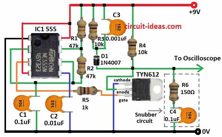
To build a Thyristor Switching using Snubber Circuit follow the below mentioned steps for connections:
- First, put all parts like shown in the diagram.
- Next, pin 1 of IC 555 connects to ground.
- Then pin 2 connect to pin 6 and also connect capacitor C1 from pin 2 to ground.
- After that, pin 3 connects to gate of SCR TYN612 through resistor R5.
- Now pin 4 and pin 8 connects to +9V power.
- Also, pin 5 connects to ground using capacitor C2.
- Lastly, put resistor R2 between pin 6 and pin 7 and then put resistor R1 between +9V and pin 7.
SCR TYN612 Connection:
- Now cathode connects to ground and anode connects to +9V through resistor R4
- Then gate connects to pin 3 of IC 555
- Next, oscilloscope connects across anode and cathode of SCR to watch output.
Snubber circuit:
- Connect from oscilloscope output with resistor R6 and capacitor C4 in series to ground.
D1 Diode part Connection:
- Connect resistor R3 and capacitor C3 in parallel and connect between +9V line and cathode of D1 and anode of D1 connect to anode of SCR.
Safety Tips:
- Know how each part works especially with snubber circuit and if not sure ask trained technician to help.
- Also, if something goes wrong then turn OFF the power immediately and fix first and then turn ON again.
- Follow safety steps to avoid damage or danger.
Conclusion:
Thyristor Switching using Snubber Circuit protect thyristor from Sudden voltage spikes and with sudden current surges.
Even if there is little difficulties while making, then snubber helps thyristor live longer and work better.
Leave a Reply