Can anyone think small timer for their electric things?
Simple Time Delay Relay Circuit work like stopwatch for power.
It waits for some time before turning ON or OFF something like light or motor.
This wait time can be same always like 5 second or can change using timer knob.
Main reason to use it is to control when thing start or stop in system.
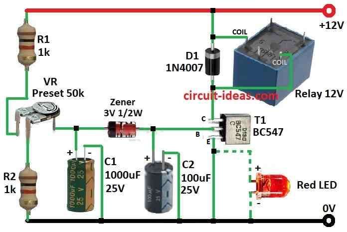
Circuit Working:
Parts List:
| Category | Component | Quantity |
|---|---|---|
| Resistors | 1k 1/4 watt | 2 |
| Preset 50k | 1 | |
| Capacitors | Electrolytic 1000µF 25V | 1 |
| Electrolytic 100µF 25V | 1 | |
| Semiconductors | Transistor BC547 | 1 |
| Zener diode 3V 1/2 W | 1 | |
| Diode 1N4007 | 1 | |
| Red LED 5mm 20mA | 1 | |
| Relay 12V | 1 |
Protect the device using this small simple time delay relay circuit.
Modern electronics use SMPS power supply which can get damage from sudden power spike.
This circuit wait for one minute before turning ON the device.
So it stop big current rush and spike at power ON.
When power comes back after the cut big current can hurt the SMPS.
This power spike happen because of strong magnetic force in power transformer.
If we wait little time before to turn ON we can stop this damage.
This time delay circuit does that which gives power to device after 1 or 2 minutes of delay when power comes back.
This circuit work like switch controlled by Zener diode.
Capacitor C1 slowly get charge through resistor R1 and VR.
When C1 voltage goes above 3V then Zener diode starts work and turn ON the transistor T1.
Relay is connected to T1 but when T1 turns ON relay also turns ON.
Then it gives power to device using relay contacts.
Relay stays on as long as power is stable.
Capacitor C2 help T1 to stay ON properly and stop relay from clicking ON and OFF.
Diode D1 stops back current when T1 turn OFF.
Red LED shows when relay is working.
Delay time depends on size of C1.
Formulas:
Formula for Time Delay Relay Circuit:
Time Constant (τ):
This is main thing to find delay time.
It is just resistance (R) times capacitor (C).
It tells how long capacitor take to charge or discharge for the needed voltage.
Simple formula to imagine delay time:
Delay Time = k × τ
where,
- Delay Time: Time in seconds (s) relay take to turn ON after power comes.
- k is fixed number which depend on transistor and how circuit is made.
- Mostly it is around 0.693 for simple circuits.
- τ (tau) is time constant.
One can find it like in the below formula:
τ = R × C
where,
- R is the timing resistor value in ohms.
- C is timing capacitor value in farads.
Important Points:
This is just rough idea but actual delay can change because of parts difference and how transistor work.
This formula works for simple circuit with one resistor and one capacitor for RC network.
Complex circuits may need different method to find delay.
How to Use Formula:
To find timing resistor Rt and capacitor Ct in the circuit:
- Multiply Rt × Ct to get τ.
- Then multiply τ × k which is around 0.693 to get delay time.
- This is easy way to guess delay time.
- For very correct result one need to use advanced tools or testing.
How to Build:
To build a Simple Time Delay Relay Circuit one need to follow the below mentioned assembling steps:
Get the Parts:
- First collect all parts needed from the list above.
Make the Connections:
- Follow these steps:
- Connect front side anode of Zener diode to base of NPN transistor T1.
- Connect back side cathode of Zener to where R1 and VR join together.
- Connect collector of T1 to one side of relay coil.
- Connect other side of relay coil to 12V power positive.
- Connect emitter of T1 to ground
- Connect one side of NO (normally open) contact of relay to 12V positive.
- Connect other side of NO to the device (load).
- Connect common pin of relay to ground
- Put capacitor C1 between Zener cathode and ground.
- Put capacitor C2 between ground and base of T1.
- Connect resistor R1 in series from VR top side to 12V power.
- Connect resistor R2 from bottom of VR to ground.
- Put diode D1 across relay coil.
- Cathode side of diode will connect to 12V. and anode side to collector of T1.
Test and Set:
- Turn ON the power and change VR slowly to adjust the delay.
- Relay will turn ON after 1 or 2 minutes.
- We can use multimeter to check the delay time.
Fix the Circuit:
- After testing and set delay properly one can build the circuit permanent on PCB or board.
Connect the Device:
- Now connect the device to relays NO contact pin.
- Device will turn ON only after the delay time, this help protect from power spike and strong inrush current.
Be Safe:
- Always be careful when working with electric circuits.
- If not sure ask help from someone who knows electronics.
Conclusion:
This Simple Time Delay Relay Circuit is easy and useful way to protect electronic devices that use SMPS power.
It waits for 1 to 2 minutes before giving power so it stops damage from big current rush and power spikes.
This make the device work better and live longer.