In this article, we will learn how a triangle wave rises and falls repeatedly.
Smaller waves, called harmonics, create this special wave and its shape looks like a triangle because these smaller waves fit together like bricks.
Harmonics in triangle wave get weak fast and is not strong like square wave, so triangle wave is more smooth and is not sharp like square wave.
Furthermore, engineers use triangle waves in signal processing, waveform generation, and testing tools.
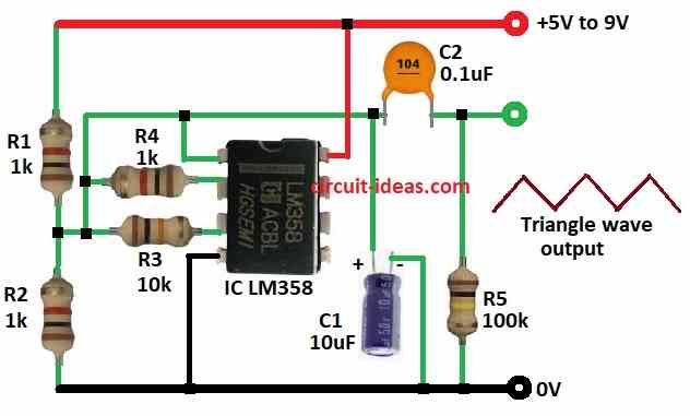
This article for Simple Triangle Wave Generator Circuit using IC LM358 show how to make triangle waves with few parts like IC, resistors and capacitors, also this circuit works with 5V to 9V power.
Circuit Working:
Parts list:
| Components | Values | Quantity |
|---|---|---|
| Resistors | 1k 1/4 watt | 3 |
| 10k 1/4 watt | 1 | |
| 100k 1/4 watt | 1 | |
| Capacitors | Electrolytic 10µF 25V | 1 |
| Ceramic 0.1µF | 1 | |
| Semiconductors | IC LM358 | 1 |
To begin with, main part in circuit is op-amp and it work like integrator and Schmitt trigger.
Op-amp from LM358 with resistors R1, R2, R3 make Schmitt trigger and this makes steady square wave by switching when input go over set voltage.
R3 give feedback and help op-amp switch clean between high and low and make good square wave.
Op-amp also work as integrator using R4 1k and C1 10µF on inverting input and then it take square wave from pin 1 and changes it to triangle wave by integrating.
So output voltage goes up and down again and again and this make triangle wave.
Formulas:
These formulas show how triangle wave circuit with LM358 op-amp works:
1. Schmitt Trigger Formulas:
Positive Threshold (Vth+):
Vth+ = Vref + (R2 / (R1 + R2)) × Vcc
Negative Threshold (Vth−):
Vth− = Vref − (R2 / (R1 + R2)) × Vcc
Vref set by voltage divider.
2. Hysteresis (ΔV):
ΔV = Vth+ − Vth−
3. Integrator Formulas
Frequency (f):
f = 1 / T = 1 / (2RC)
Period (T):
T = 2RC
where,
- R is R4 and C is C1.
4. Slope of Triangle Wave:
Slope = (Vmax − Vmin) / (T / 2)
where,
- Vmax and Vmin are top and bottom of wave.
5. Integrator Output Voltage:
Vout(t) = ∫Vin(t)dt
This means voltage goes up and down to make triangle shape and these formulas help us understand and check how triangle wave circuit works with LM358.
How to Build:
To build a Simple Triangle Wave Generator Circuit using IC LM358 follow the below mentioned steps for connections:
- First, put all parts as per circuit diagram.
- Next, connect pin 1 of LM358 to triangle wave output using capacitor C2.
- Then connect pin 2 to pin 1 using resistor R4.
- Now connect pin 3 to pin 1 using resistor R3 and also pin 3 goes to point between R1 and R2.
- After that, connect pin 4 to GND and connect pin 8 to positive supply.
- Also, connect resistor R1 and R2 between positive supply and GND.
- Finally, connect capacitor C1 between pin 1 and GND and also connect resistor R5 from output of C2 to GND.
Conclusion:
To conclude, Simple Triangle Wave Generator Circuit using IC LM358 is simple and easy to build.
Also, change resistor and capacitor values to adjust wave frequency and size; in addition, this circuit is good for electronics testing and making projects.
Leave a Reply